Interfacing a PC/AT-compatible Keyboard by Lee Davison
Hardware
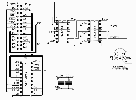
The connector on the top left of the diagram is from my own 6502 boards
and is as it is for two reasons. It's easy to wire on a stripboard layout
and I have a lot of 26 way ribbon, headers and plugs. All the signals
are directly from the 6502 except /SEL0 and /SEL1 which are used to
select the block $F1xx with /SEL0 = 1 and /SEL1 = 0.
The 5 pin DIN socket is shown looking at the holes of the socket.
The circuit is built on stripboard. Layout is not critical, power is
linked using 0.8mm uninsulated copper (the centre from tv coax, or
similar, is ideal) and the logic is wired on the print side with self
fluxing 32swg enamel covered copper wire. The header and DIN socket were
re-cycled froma dead PC motherboard using a 750w hot air paint stripper.
The two capacitors are low ESR electrolytics and are placed near the GAL
and near the keyboard socket. If you don't have this type to hand you can
use standard electrolytics with some low value caramic capacitor, say
0.1uF, in parallel.


The GAL16V8A is used purely to generate the read and write strobes. Each
is a negative going pulse coincident with phase 2. The interface uses just
one byte in the address range. For anyone interested the equations for
this chip are in atkey_01.pld and can be
compiled with WinCUPL. The fuse
file, atkey_01.jed, is also included.
The 74LS74 is used to latch the two lowest bits of the data bus during
write access to the interface. The reset line is connected so that both
of these outputs are cleared at startup (this disables the keyboard until
required).
The outputs from the latches are used to drive the enable pins on two of
the four buffers from the 74LS125, these are then used to drive the data
and clock lines of the keyboard. The buffers have their inputs tied
low so behave like open collector outputs when used like this.
The other two buffers are used to drive the data bus during read access.
Note that the keyboard supplies the pullup for both the data and clock
lines so with no keyboard connected you may read zero when you expect a
one.
Software
The software required to read and decode a PC/AT-compatible keyboard is
somewhat larger than the average hardware mini-project. The source code
can be downloaded from here: kbd6502s.txt.
The software has a few basic routines to raw handle the keyboard...
- ResetAT
This routine sets the pointers to the decode table, clears
the lock LEDs and the key status bits for the decode routine.
Finally it resets the keyboard.
- KeyLEDs
This routine sets the keyboard lock LEDs from the lock LED
status byte. Only bits 0, 1 and 2 are used.
- ScanAT
This routine scans the keyboard to see if a scancode is
waiting. If not it will return with A and RxChar set to zero
after about 300uS, otherwise it will return the scancode in
A and RxChar.
As well as matrix scancodes possible bytes returned by
this routine are ...
$00 - No key waiting
$AA - Power On Self Test Passed (BAT Completed)
$EE - See Echo Command (Host Commands)
$FA - Acknowledge
$FE - Resend
$FF - Error or Buffer Overflow
- SendAT
This routine is used to send command and control bytes to
the keyboard, the codes are ..
$ED - Set the LEDs according to the next byte I send
bit 0 = scroll lock
bit 1 = num lock
bit 2 = caps lock
bits 3-7 must be 0, 1 = LED on
$EE - echo, keyboard will respond with $EE
$F0 - set scan code set, upon sending the keyboard will
respond with ACK ($FA) and then wait for a second
byte. sending $01 to $03 determines the code set
used, sending $00 will return the code set currently
in use.
$F3 - set typematic repeat rate, upon sending the
keyboard
will respond with ACK ($FA) and then wait for a
second
byte. this byte sets the rate.
$F4 - keyboard enable, clears the keyboard buffer and
starts
scanning.
$F5 - keyboard disable, clears the keyboard buffer and
stops
scanning.
$F6 - restore default values upon sending the keyboard
will
respond with ACK ($FA)
$FE - retransmit the last character please, upon
sending
the
keyboard will respond by resending the last character
$FF - reset, you stupid keyboard
There is one routine to make the keyboard look something like a
standard ASCII character device. This is...
- ScanKey
This routine checks for a key waiting and if there is will
decode it to ASCII and return it in RxChar, else, on return,
RxChar will be null. Note some valid key actions will result
in a null return such as control, shift and lock keys and any
undecoded key (cursor keys for example).
Notes on the Decoding Table
Most AT keyboard decoding software uses two tables, one for the
unshifted characters and one for the shifted characters, some use further
tables for control and alt character decoding as well. In this software
The normal and shifted characters are held in the same table but shifted
half the table length. This only causes a problem with the numeric pad
slash character, /, but this is corrected with a small bit of extra
code. Also some special characters, ª and œ (uk keymap), are outside the
normal ASCII range. These are also handled by some extra code. Control
characters are handled entirely by code as it is far cheaper, space wise,
to do this.
The function keys each generate a unique code but this is not output by
the routine, neither is the Win menu key code. It is left to the user how
to use these keys. Cursor control keys are not coded as this interface was
for a system without a screen type display, but this could easily be
changed by adding the desired codes to the decode table.
Lastly the table overlaps the RTS of the last subroutine. This is not a
mistake, the first byte in the table is never used so this will save a
byte without penalty. For the same reason the table stops two bytes short
of the end, again with no real loss. If space on the target system was
really tight then some parts of the code could even be moved into the
table, saving about fourteen bytes in total at the cost of a small slow
down and increased stack use.
Using the Routines
To save code, time and space nearly all of the subroutines rely on the
values held in two or more registers upon calling and some routines rely
on register values and flag states returned. If you are going to change
the code read the comments carefully before changing any parts to ensure
you don't violate any of these requirements. The code is fully commented.
A Final Thought.

With the addition of two 4k7 resistors this interface would be ideal for
use as an I2C bus master. As I have an I2C bus teletext card I may do
just that.
Last page update: March 27, 2001.