Data Pod by Samir Lohani
The Data Pod (or DPOD) is a pluggable serial EEPROM based secondary storage for use with PCs and microcomputer boards. Early microcomputers such as KIM, SYM provided a cassette interface for secondary storage. Having built a 65C02 based microcomputer board , I was reluctant to provide for the obsolete cassette interface or an extensive Floppy drive interface for secondary storage and porting of programs and data. The data pod module was therefore designed to provide nonvolatile secondary storage (presently 64K bytes) which can be connected to the microcomputer board as well as to modern PCs via the serial port. This has proved extremely useful for transporting programs and data from IDE running on PC to the microcomputer board much like a PCMCIA flash card used with laptops.
The data pod has been designed to connect to the PC RS232 serial port or to the microcomputer I/O ports without any glue logic. When connected to RS232 serial port, the unit withstands the harshest RS232 levels / transients. The unit draws its power from the RS232 port and is hot-pluggable. When connected to the (65(C)02) microcomputer board, no additional interface hardware is required. Other than +5V and 0V , only three free port lines are required (the cassette interface also required three port lines for data-in, data-out and motor-relay). These can be connected directly to port pins (Port A or Port B of PIA / VIA chip) or to buffered port pins where available or simply to the 3 port lines (2 output + 1 input port line) of the existing cassette interface. The interface is compatible to TTL / CMOS / Open drain port lines. All connections are made through the 9 pin connector on the DPOD board. There is no separate connector for power supply. Further in both the above configurations, the unit is protected against wrong connections ( which is fairly common in the RS232 world) and ESD damages.
This board can also be used as a generic I2C interface. By connecting a PCF 8574 IC, the interface may be turned into a 8 bit I/O port, or it may be used to program the DS 1621 Thermostat chip of Dallas semiconductors. Several more applications of the circuit can be easily thought of.
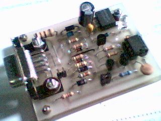
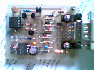
The DPOD board is constructed as a compact card
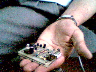
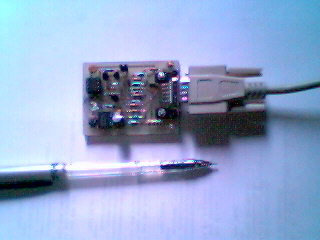
These photos illustrate the size of DPOD board
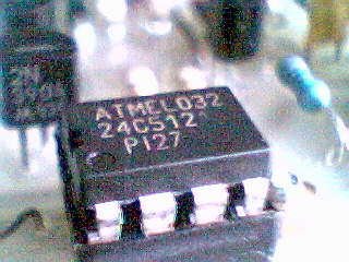
A close-up of the serial EEPROM fitted in DPOD (here ATMEL 24C512)
Connects to PCs via the serial port (COM1/COM2)
Interfacing circuit incorporates protective
features for:
- Wrong connections / use of wrong cable
- Over-voltage / Non standard RS232 levels
- Software error - hardware ensures that if Vcc to IC is not
switched on , all inputs to IC are disabled.
- ESD protection
Supports 'hot-plugging' to the serial port ( no need to switch PC supply off )
Circuit designed to connect to most microcomputer ports directly without any 'glue-logic' or voltage converters
Can also be used as a serial EEPROM programmer, I2C interface, Programmable data / program cartridge for microcomputers
Driver software written in C.
The block diagram of DPOD is shown below:
A DB9 female connector X1 is provided on the DPOD board and handles all interfacing requirements.
When connected to
a PC RS232 port, the TXD line is used to provide +5V regulated power to the
entire circuit (Block A). The open collector inverting buffers (Blocks B and C)
connect to RTS and DTR signals respectively to generate I2C signals SCK and SDA.
The status of the SDA line can be read via the inverting stage (Block D) on the
CTS line. Jumper JP1 when plugged pulls the Write Protect pin (WP pin) of the
EEPROM low to enable writing to the EEPROM. If JP1 is removed, the EEPROM is
partially/fully write protected (see datasheet of relevant EEPROM).
Note that WP, SCK and SDA are pulled up to Vcc through pull up resistors R8,
R7 and R9. These lines are either at logic low level (< 0.4 V) or pulled up
to Vcc. If the power to the circuit is shut off, the voltage on these lines also
falls and never exceeds the Vcc to the EEPROM. Also note that jumper JP2 is not
plugged in this application, but if it is inadvertently left plugged, the DPOD
software merely reads the jumper status at DCD pin and displays it to the user.
In case of a microcomputer board, either a RS232 connection can be used as above or microcomputer port pins may be directly used. In the latter case, buffers B, C and D work equally well at TTL/CMOS port pin levels. The system Vcc of +5V is given to DCD pin on X1 while TXD pin may be left open or grounded. Jumper JP2 is then installed. The special low dropout voltage regulator ensures that the dropout voltage remains within 100mV typical. Thus EEPROMS in 5.0V versions (Vcc=4.5V to 5.5V) and 2.7V versions (Vcc=2.7V to 5.5V) can be used in dpod.
The detailed circuit is shown below:

This circuit closely corresponds with the block diagram. Diode D1 protects the power supply against reverse voltage. Resistor R1 is provided for 2 reasons - to limit worst-case inrush current during hot-plugging / overvoltage and as a simple means of measuring current drain of the circuit while plugged in the PC and running a diagnostics program. It is possible for the diagnostic program to selectively switch on the power supply and the EEPROM IC from standby to active mode while the voltage drop across R1 is measured with a DMM to deduce the current drain. The current drain of the DPOD board is well within 5 mA which can easily be sourced by the TXD line.
The voltage regulator is a National Semiconductor micropower LDO regulator type LP2954AIT. This is available in a 3 lead plastic TO-220 package. For this circuit, the important features of this IC are tight regulation, low dropout voltage, extremely low quiescent current (120 microamp at dropout), wide input supply rating (-20V to +30V) and output isolation( output can be left connected to an active voltage source without power supply to IC input - this presents interesting expansion possibilities in that the interface can also be used as part of a bigger circuit drawing power from it). The output capacitor C2 is a tantalum type because of its good ESR properties and D2 is a high intensity LED with transparent lens so that glowing of the LED with extremely low forward current is seen easily. LED D2 indicates power switched on to the DPOD board.
The open collector inverting buffers connected to RTS and DTR are compatible to both RS232 and microcomputer I/O ports. Since 2N3904 transistors require a base current of only 5 uA to switch SCK and SDA low, pull down resistors R10 and R11 ensure a switching threshold of 1.1V and stable behaviour of the circuit when connected to microcomputer ports which are defined as inputs after reset and do not have a internal pull up resistor ( such as B port lines of 65(C)22 / 6532). The input current requirement of 60 uA is easily sourced by totem pole type ports or open drain ports with pull up resistors. Thus the input buffers can be connected either directly to microcomputer I/O ports or via any buffered port lines available. The input stages also withstand accidental high input voltages and ESD surges encountered in harsh environments.
The output inverting stage D uses a MOSFET BS170 to drive the CTS line. This MOSFET has a drain-source on resistance of only 5.0 ohm. Resistor R6 and schottky diodes D5 and D6 provide protection in case of wrong connection. Note that using a MOSFET to sense SDA isolates the I2C section from the interface side voltages. The pull up resistor R5 and clamping diode D6 is also connected to input of IC1 and the output high voltage level therefore depends on input supply voltage level, whether through TXD or DCD line. The output stage is also compatible with RS232 or +5V microcomputer ports and can be connected to any input port pin directly or via a buffer stage available on the microcomputer board.
Note: Due to high pull up resistances used to minimise current drain of the circuit, Q1 and Q2 must be selected so that the collector leakage current Ico is within 5 uA. Most transistors have Ico within this limit.
The EEPROM is wired with select lines A0, A1 and A2 at logic low. No attempt has been made to use EEPROM banks on DPOD as EEPROM capacities are increasing rapidly. Note that the I2C/ Extended I2C standard has a theoretical addressing limit (2Kbytes for I2C, 512KB or 1MB for Ext I2C) and going by the rate at which EEPROM capacities are doubling in the same package, it is only a matter of time before the entire addressing capacity of Ext I2C is usable in only one chip.
The WP pin is pulled high by R8. Though low current internal pull-up / pull-downs are provided in several modern EEPROMs, R8 and JP1 ensure compatibility with a wide range of EEPROMs.
A variety of serial EEPROMs can be used in the DPOD board. I have tested the DPOD board with NM24C17 EEPROM (2 Kbytes, Fairchild Semiconductor, I2C interface) which incidentally I obtained as a free sample and Atmel EEPROMs AT24C256 / AT24C512 (32Kbytes / 64Kbytes, Extended I2C protocol).
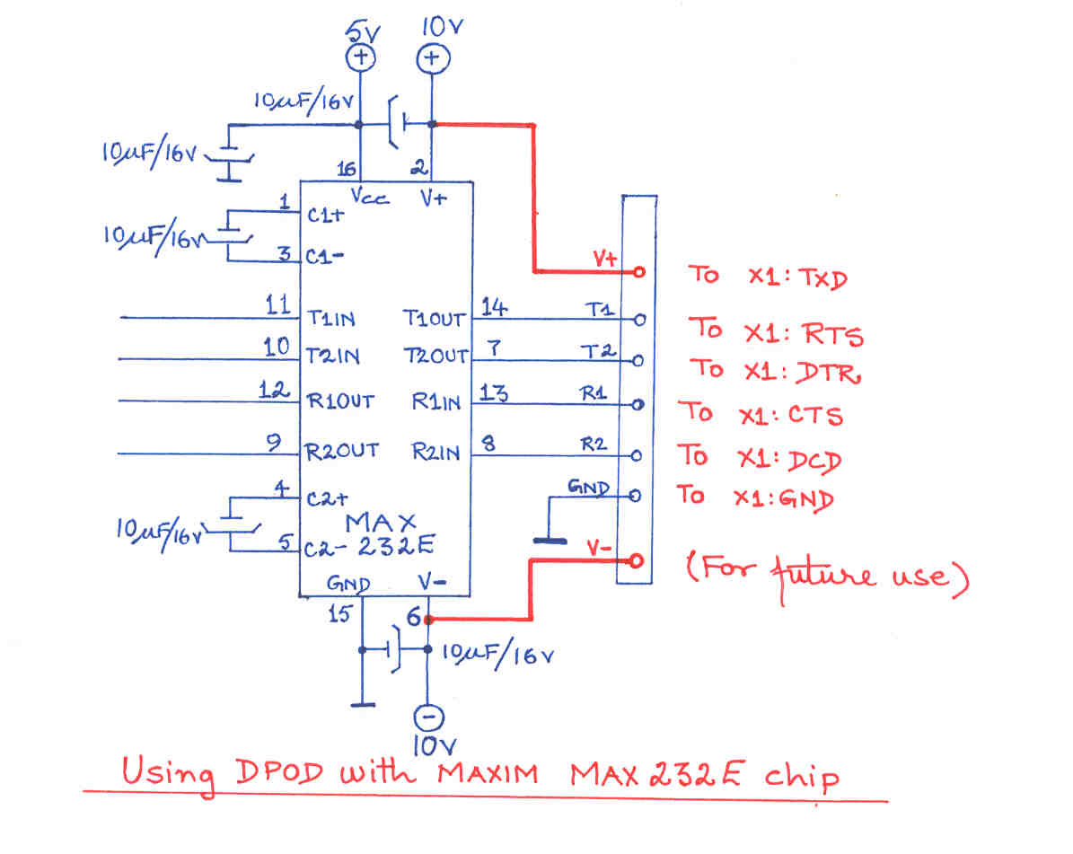
A full serial port is not implemented in many microcomputer boards . My 65C02 microcomputer uses a MAX 232E chip for the serial interface. This chip has two RS 232 output lines while the DPOD board requires three. The following modification (shown in red) needs to be carried out if it is desired to use the same serial port for driving the DPOD board:
| R1 | 100 ohm, 1 Watt |
| R2, R8 | 22K, 250mW |
| R3, R4, R5 | 6.8K, 250mW |
| R6 | 100 ohm, 500mW |
| R7, R9, R10, R11 | 10K, 250mW |
| C1 | 22uF / 63V |
| C2 | 4.7uF / 35V Tantalum |
| C3 | 100nF Ceramic |
| D1 | 1N4007 |
| D2 | Red high intensity LED with transparent lens |
| D3, D4 | 1N4148 |
| D5, D6 | 1N5819 Schottky diodes |
| DZ1 | 24V, 1 Watt Zener |
| Q1, Q2 | 2N3904 |
| Q3 | BS170 MOSFET |
| JP1, JP2 | Jumpers SIL 2 pin |
| IC1 | LP2954AIT (National Semiconductor) |
| IC2 | EEPROM (Atmel AT24C512 may be used) |
| X1 | DB9 female connector PCB mount type |
| Miscellaneous | 8 pin DIP socket for IC2 |
| 2 Jumper plugs for JP1, JP2 | |
| PCB set |
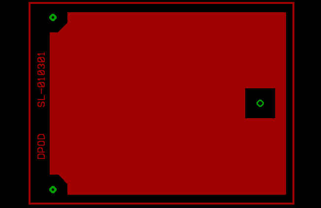
The PCB of the project designed in Eagle Layout Editor measures just 2.6" x 2.0" . A screenshot of the PCB component layout is shown below:
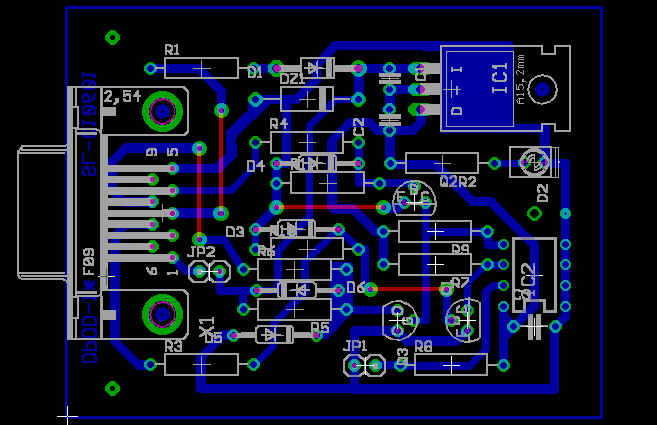
This is a single sided PCB (The red lines are wire jumpers to be soldered on the PCB). A second single sided PCB is designed to serve as a base plate screen which is connected to ground by a short jumper wire. Three holes are provided for 'sandwiching' the two PCBs by means of spacers. The tin plated tracks of both PCBs face each other.
This method of construction ensures that no 'cabinet' needs to be constructed for the DPOD. The photographs given in the beginning of the page may be referred to for an idea of construction details.
The board files for Eagle Layout editor for the top component layout PCB and the base plate PCB may be downloaded from the hyperlinks provided.
After soldering the components on the PCB, the PCBs should be degreased and protected by a thin coat of PCB acrylic lacquer aerosol.
Software for the project was written in C and compiled using Turbo C++ 3.0 . I am releasing the source and executable files to the public domain on 'as is where is basis' provided only that the copyright messages be retained and due acknowledgements given when using the material of the files.
The program runs under MS-DOS and allows writing or reading a block of arbitrary length from the DPOD. The program supports 3 EEPROM types : 24C16/24C17 (Highest capacity (2KB) EEPROM of I2C protocol), 24C256 (32 Kbytes) and 24C512 (64 Kbytes) EEPROMS (Extended I2C protocol). The program supports either COM1 or COM2. For details on usage, see readme.txt file.
Note that Windows GUI release 95 and later make it no longer possible and even forbidden to communicate directly with various registers and memory locations as this task is left to the operating system in conjunction with various device drivers. The DPOD program must therefore be run from the MS-DOS command line prompt (press F8 after power on and choose 'Command line prompt' mode). The program may not run properly in Windows MS-DOS Prompt unless the COM port driver has DOS box support. If DPOD 'Power on LED' does not light and the program DPOD returns an error message while accessing DPOD, ensure that it is running in MS-DOS command line prompt mode.
Run DPOD program without any options for a listing of the command line options supported.
The source program written in C is extensively documented and the hardware dependent RS232 functions are separately listed. On similar lines, a assembly language program for accessing DPOD through the 65(C)02 based microcomputer may be written. The program takes all input through command line parameters and writes operating parameters and error messages to the standard output which can be redirected to a file or a printer. This is done to enable spawning the program from a higher level C program or batch file for more complicated operations and to have a written log of operations on a printer. The program also lists out a 16 bit CRC word which is based on the CCITT error checking polynomial. This CRC word should be the same during Read and Write operations on the same data block.
Finally a note for 65(C)02 programmers: There is a minor difference in using Port A and Port B lines of PIA/VIA for the two output lines RTS and DTR. With Port B lines, these are defined as inputs at Reset and correspondingly SCK or SDA are held high which should be the normal state of the lines. In this case, first '0' may be written to Data Register and then these lines defined as outputs by writing the Data Direction Register.With Port A lines, these lines are pulled up high at Reset by the internal pull up resistors of the VIA/PIA chip and so SCK or SDA go to the low state. This may be treated as an interruption in I2C communication and a Reset procedure must be initiated after Reset. The Reset procedure has been outlined in the C source file discussed later.
Here are some snapshots of the program output:
Reading file from DPOD and saving in desktop:
dpod -r -l4c02 c:\windows\desktop\dpod.c
Download the DPOD archive containing the C source file, the executable file and readme.txt file from here.
Since several 65(C)02 microcomputer boards including mine use a 32 KB battery backed up RAM, I am working on design of a small file-handling software which recognizes both system Battery Backed up RAM and the plug-in DPOD as separate compatible 'drives' and supports DOS like operations of load, save, verify, rename, copy, compact , backup etc while merging seamlessly with the operating system. On the PC side, Windows support would be an essential requirement.
Here are the manufacturer's datasheets for the EEPROMS / ICs :
National Semiconductor's application note on using I2C EEPROMs
The New I2C bus specification may be found here.
( The Manufacturers' copyrights may be duly consulted for using these documents)
Samir Lohani may be contacted at slohani90182@yahoo.com
Last page update: October 18, 2000.