 ---------------------------------------------------
| The engineer explains/presents his plans          |
| to a large audience. At some point,               |
| people are starting to get a bit anxious,         |
| until eventually one in the audience dares        |
| asking the question:                              |
|                                                   |
| "But how to get the crew back from the Moon       |
| after they landed there ?"                        |
|                                                   |
| The engineer is getting upset:                    |
| "The request for bids only was about bringing     |
| a man to the Moon. There never was any discussion |
| about bringing him back !"                        |
 ---------------------------------------------------
Once upon a time, when industrial control of machinery
was done by big/clumsy cabinets/switchboards, people soon
discovered that changing the (manually) wired functionallity
was not easy.
Electricians/Engineers spent more than eight hours a day
inside cramped cabinets, between all that wires and components,
and tried to fix one (unforseen) problem, without causing the next.
Actually, there even whas a joke, that control cabinets
were sold together with an integrated Technician.
Would have been nice to have something versatile, programmable...
Those, who did not believe in computers/processors built sequencers.
Basically a counter, connected to the address lines of some kind of ROM,
that gave out the control signals at the data outputs.
In some cases, it was necessary to test the status of some
input signals from the machinery (limit switches, for instance)
and to alter the sequence of control words.
With a few tricks, and some additional circuitry between
status inputs and counter, it was possible to jump to a given
counter location, or to skip the next control word.
However, said circuitry could become a little bit complicated.
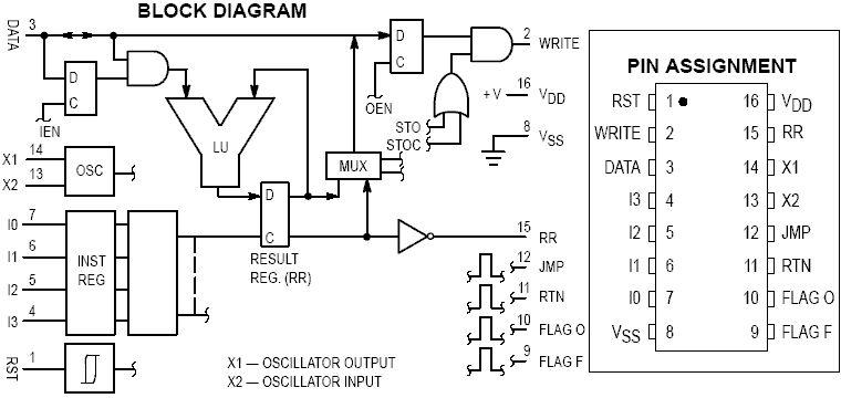
An alternative was the MC14500. It was able to control
the counter, to read inputs, and to write outputs.
The MC14500 is an odd/unique design, that can't be categorized easy.
It shows program flow control like a simple RISC (skip next Opcode
if result is zero, JMP, JSR, RTS), combined wit a one Bit Logic Unit
(no arithmetic at all !)
Still undecided, if it's a processor or not.
4 Bit Opcode, 1 Bit Databus, Program memory and Data memory
are separated.
RR,  or Result Register, was used as accumulator.

O_EN enabled/disabled write access to data memory.

I_EN was used to force a read value from data memory to Zero.
This way, it was easy to emulate flipflops, and to save
a few conditional jumps.
Opcodes:

0x0 Flag 0 // Emit pulse on FLAG_0 Pin
0x1 LD     // RR =  (D_IN & I_EN)
0x2 LDC    // RR = !(D_IN & I_EN)
0x3 OR     // RR = RR |  (D_IN & I_EN)
0x4 ORC    // RR = RR | !(D_IN & I_EN)
0x5 AND    // RR = RR &  (D_IN & I_EN)
0x6 ANDC   // RR = RR & !(D_IN & I_EN)
0x7 XNOR   // RR = RR ^ !(D_IN & I_EN)
0x8 STO    // Write  RR to data memory, if O_EN = 1
0x9 STOC   // Write !RR to data memory, if O_EN = 1
0xa IEN    // I_EN = RR
0xb OEN    // O_EN = RR
0xc JMP    // jump
0xd RTN    // return from subroutine (ignore next opcode)
0xe SKZ    // skip next opcode, if RR is Zero
0xf Flag F // Emit Pulse on Flag_F Pin
Decided to use Flag 0 as NOP, and Flag F as JSR.
LD  0 // RR   =        I_EN & DIN
ORC 0 // RR   = RR | !(I_EN & DIN) = 1
IEN   // I_EN = RR
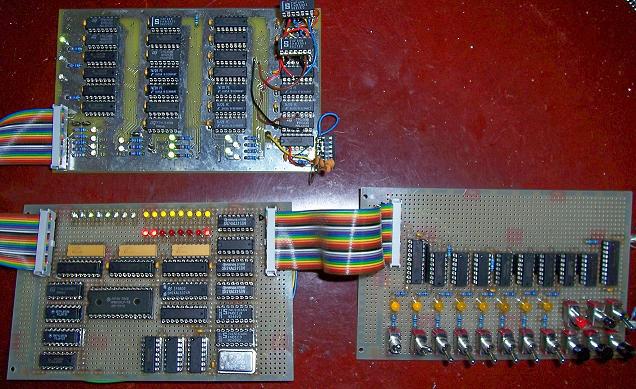
Tried to build something binary compatible with NAND gates.
It turned out to be not so useful at all, but it gave me a few
inspirations for ALU design and timing.
WARNING: the design had a few bugs.
Fixed them in layout and schematic, but didn't build
this version for verification.
Do not expect it to work at all.
Better go with GAL22V10 than with NANDs.
28 ICs: 14*7400, 6*7410 7*7420, 1*7430.
Decided to use low_active outputs, most of them not pulsed,
because the PC was done with syncronous counters.
Note, that this schematic/layout does not contain I/O,
program/data memory, program counter, or return stack.
It's only the "CPU".
The CPU:
| Datei // File | Beschreibung // Description |
| m14500v1.brd | Layout (Eagle 3.55) |
| m14500v1.sch | Schematics (Eagle 3.55) |
Schematics in JPG format:
[2016: Edit:                                           ]
[                                                      ]
[ And this also was proof that building a 'Logic Unit' ]
[ with multiplexers actually works.                    ]
More technical details in the "articles" section:
(c) Dieter Mueller 2004,2005