An experimental attempt of building something like a 6522
with 74XX TTL chips.
The design might have some issues,
try reading the schematics at your own risk...
you better check, if the circuitry which detects timer overflow
works as intended... I think it doesn't work as intended.
I\O and bus connectors are supposed to be compatible
to Daryl Rictor's SBC-2.
It was the first project after two years of inactivity,
and I had some problems getting started with hobby electronics again,
so a few things might not be optimal...
like placement of some of those 100 nF capacitors.
X22 seemed to have worked with a Rockwell R65C02-2
running at 4 MHz.
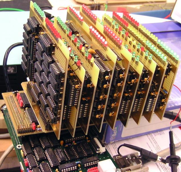
Test setup:
Bottom: my DRC2 SBC, which is supposed to be compatible to the SBC-2.
2B22 bus interface is plugged into DRC2.
X22 backplane is plugged into the 2B22 bus interface.
Plugged into the X22 backplane, we have:
1* 1PA22, Port A module
1* 1PB22, Port B module
2* 1H22, handshake module
2* 1T22, timer module
1* 1TC22, timer control module
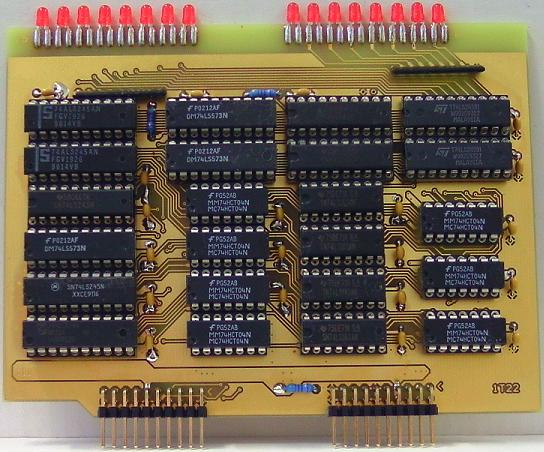
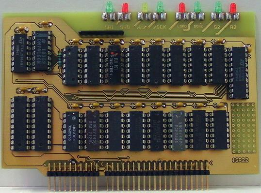
1* 1SR22, shift register module
1* 1I22, interrupt module
X22 backplane:
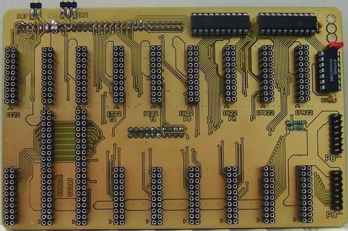
Jumper\switch in the upper right area is for enabling the blinkenlights.
Two pin jumper in the upper left area only is for testing the hardware
without 1TC22 and 1SR22, leave it OPEN.
Three pin jumper in the upper left area is for connecting
the interrupt output to either NMI or IRQ.
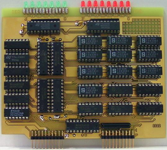
2B22 bus interface
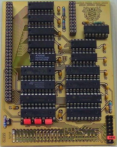
The jumper field in the lower right area is for the chip select.
The jumpers in the lower left area are for deactivating
some of the address lines when using the bus interface
in a project which requires less than 16 registers.
For the X22 project, set them as marked on the PCB.
1PA22 Port A module
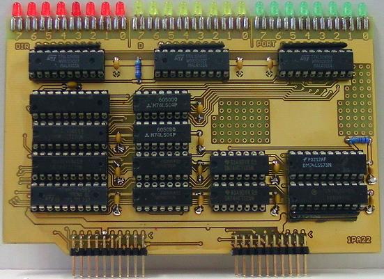
Port A has open collector outputs.
There is a pullup resistor network for the port lines
in the schematic and layout of the port lines.
I suggest to solder a single row precision socket into the PCB,
to make sure that you are able to try different resistor values,
or to go without pullup resistors if necessary.
1PB22 Port B module
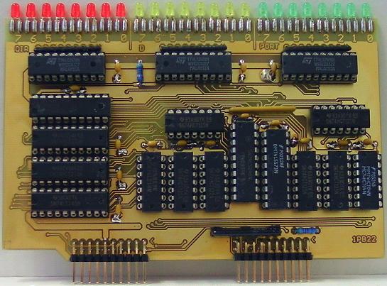
Port B has three state outputs.
There is a pullup resistor network for the port lines
in the schematic and layout of the port lines.
I suggest to solder a single row precision socket into the PCB,
to make sure that you are able to try different resistor values,
or to go without pullup resistors if necessary.
BTW: Port A module and Port B module have identical pinouts.
1H22 handshake module
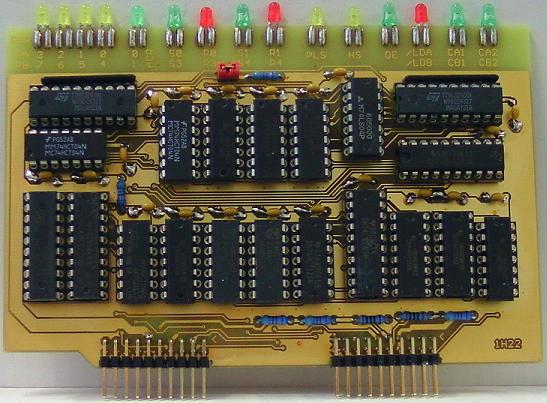
Two identical handshake modules required.
One handles CA1 and CA2, the other handles CB1 and CB2.
I suggest to set the jumper to:
CLOSED when the module handles CA1 and CA2,
OPEN when the module handles CB1 and CB2.
1T22 16 Bit timer module
Two identical timer modules required,
one works as timer 1, the other as timer 2.
Timer 2 has less functionality than timer 1,
so the module which does timer 2 would require less chips
than the module which does timer 1.
For more details, see page 1 of the schematics.
...Nevertheless, it simplifies testing when just soldering
all of the ICs into both PCBs.
BTW: failed to buy synchronous down counters.
So I just took 74163 synchronous up counters
and inverted their inputs and outputs with 7404,
to make them up_counters look like down_counters
for the CPU...
1TC22 timer control module
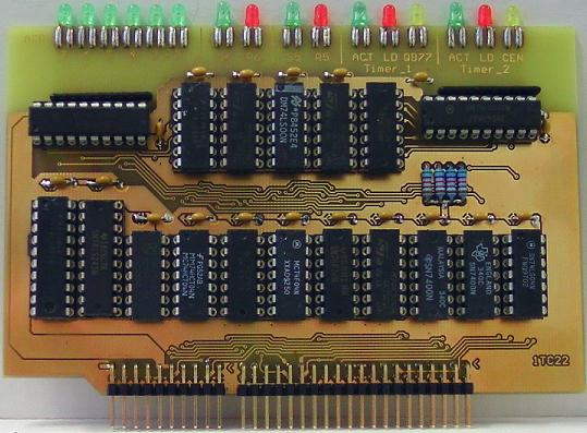
This module controls timer 1 and timer 2.
1SR22 shift register module
The 6522 shift register with all these odd operating modes...
Except that the 1SR22 has separate shift registers
for transmit and receive.
When 1SR22 shifts out data, it also shifts in data from PB5,
what allows "full duplex mode".
1I22 interrupt module
Interrupt: status and enable Bits.
The 100 nF capacitors are hidden below the IC sockets.
(c) Dieter Mueller 2015