But back to Relays.
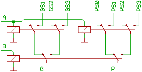
Here an example of how to build two 4:1 multiplexers,
which route the inputs PS0..PS3 to P, and GS1..GS3 to G,
depending on the signals at the select lines A, B.
To make it look more simple:
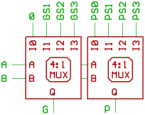
Now imagine, we would remove the two relays connected
to A, B which emit the propagate/generate signals in our
four relay adder, and use the two 4:1 multiplexers instead...

Some examples for configurating the multiplexers
to work as Logic Units:
  GS   PS
 3210 3210

 0000.0000 Q=0x00
 0000.1111 Q=0xff

 0000.1010 Q=A
 0000.1100 Q=B
 0000.0101 Q=/A
 0000.0011 Q=/B

 0000.1110 Q= A| B
 0000.1101 Q=/A| B
 0000.1011 Q= A|/B
 0000.0111 Q=/A|/B

 0000.1000 Q= A& B
 0000.0100 Q=/A& B
 0000.0010 Q= A&/B
 0000.0001 Q=/A&/B

 0000.0110 Q=  A^B
 0000.1001 Q=/(A^B)

 1000.0110 Q=A+B
 0100.1001 Q=/A+B=B-A
 0010.1001 Q=A+/B=A-B

 1010.0000 Q=A<<1 //shift left
 1100.0000 Q=B<<1 //shift left
You might want to tie C_IN inactive for logic functions,
and shifting an input right will take some additional circuitry.
Also, note that C_IN is a high active carry for A+B,
and a low active borrow for A-B and B-A.
By the way, GS0 always seems to be 0 for all combinations
that make sense.
Nevertheless, it's interesting that we could build
a one Bit ALU slice with more functionality than the 74181
by using only five relays.
(four, if one of them happens to have enough switches.)
For more details about multiplexer based ALUs,
please consult/dissect my previous two articles
about ALU design.
[2016: Edit: You recognize the pioneer by the arrows in his back.             ]
[Don't miss Jeroen Brinkman's Mercia Relay Computer ALU based on multiplexers.]
[HOME] [UP]/ [BACK] [1] [2] [3] [4] [5] [6] [7] [8] [NEXT]
(c) Dieter Mueller 2008