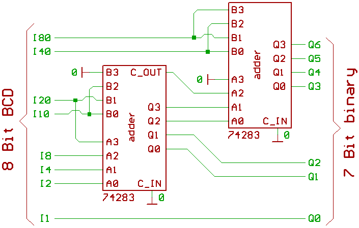
The BCD inputs are weighted like this:
10=2+8
20=4+16
40=8+32
80=16+64
Since 2,4,8,16,32,64 are pretty straight binary numbers,
it's easy to see why one BCD input signal connects to two
adder inputs in the schematic above... at least for me.
For 8 Bit binary to BCD conversion, you better use EPROMs,
sorry.
Found some neat schematics in:
TTL Kochbuch, TI Germany, 1980,
ISBN 3-88078-002-1.
Once there was another concept, called Excess 3.
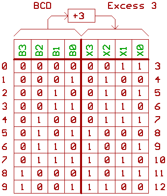
Basically it looks like adding 3 to the BCD code.
Point is, that the book claims, that using this sort
of code simplifies decimal adder circuits.
If you happen to have 4 Bit binary adders,
converting BCD to Excess 3 and back is simple:

We could draw the Excess 3 to BCD conversion a bit different:

Converting BCD to Excess 3 by using logic gates:

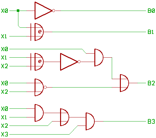
Unfortunately, I had no example for converting
Excess 3 back to BCD by using logic gates.
Here we go:
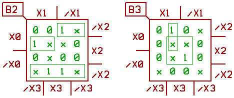
Schematic for converting Excess 3 to BCD:
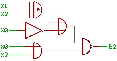
An alternative version for generating the B2 signal:
[HOME] [UP]/ [BACK] [1] [2] [3] [4] [5] [6] [7] [8] [NEXT]
(c) Dieter Mueller 2012