After building an ALU with transistors,
I figured out that the multiplexer_ALU
from my first article could be optimized.
For A+B, the old design used an OR gate
for producing the propagate_signal.
Figured out, that using an XOR instead would be better.
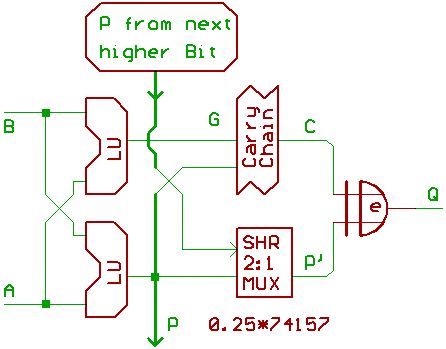
Simplified block diagram, one Bit shown:
For those, who didn't read the first article:
The 74153 contains two 4:1 multiplexers.
If we want to use such a multiplexer as a configurable
logic gate (or LU, logic unit), all we have to do is
to use the select inputs as data,
and the data inputs as select.
To make it short, the ALU inputs A,B are used as
select lines, and some sort of lookup_table is placed
at the 4 data inputs of each multiplexer to define
the results.
The two multiplexers produce the propagate and generate signals.
Example: For A+B:
Propagate means, one ALU input is 1, and the input carry
will be propagated to the next higher Bit.
Generate means, both ALU inputs are 1, and a carry
will be generated for the next higher Bit.
As we know from school, the sum of a binary full adder
can be generated with two XOR gates.
So for adding two Bits, we configurate the propagate LU
to XOR, and feed this signal into another XOR, together
with the carry input. That's all.
Shifting the Bits left is, basically, a special form
of addition.
Shifting right requires a 2:1 multiplexer.
Now the lookup_tables for the LUs:
GS0..3 is connected to the data inputs of the generate LU,
PS0..3 is connected to the data inputs of the propagate LUs.
  GS   PS
 3210 3210

 0000.0000 Q=0x00
 0000.1111 Q=0xff

 0000.1010 Q=A
 0000.1100 Q=B
 0000.0101 Q=/A
 0000.0011 Q=/B

 0000.1110 Q= A| B
 0000.1101 Q=/A| B
 0000.1011 Q= A|/B
 0000.0111 Q=/A|/B

 0000.1000 Q= A& B
 0000.0100 Q=/A& B
 0000.0010 Q= A&/B
 0000.0001 Q=/A&/B

 0000.0110 Q=  A^B
 0000.1001 Q=/(A^B)

 1000.0110 Q=A+B
 0100.1001 Q=/A+B=B-A
 0010.1001 Q=A+/B=A-B

 1010.0101 Q=A+$FF=A-1
 1100.0011 Q=B+$FF=B-1

 1010.0000 Q=A<<1 //shift left
 1100.0000 Q=B<<1 //shift left
For most commands (those who make sense),
GS0 is inactive.
If we only want to have a limited functionality
like with the 74181 (no B-A, no shift left B),
GS2 is inactive.
In that case, we don't make use of all the logic gates
inside 4:1 multiplexer that produces the generate_signal.
[HOME] [UP]/ [BACK] [1] [2] [3] [4] [5] [6] [7] [8] [NEXT]
(c) Dieter Mueller 2005