We travelled far through the land of bipolar logic design.
But modern microprocessors use MOS transistors.
MOS field effect transistors have a very low input current,
and it's possible to build nifty switches
(as known from analog sample & hold amplifiers).
You could use 74HCT4066 for experimenting.
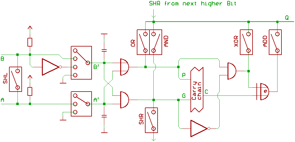
Now to describe, what one Bit of ALU in a microprocessor
could look like:
A,B are the two ALU_input busses.
If no register connects to a bus, the bus is set to -1
(all Bits high) by the pullup_resistors.
What means, for decrementing A:
No register is connected to B, so B=-1.
We are passing A,B through to A',B'.
Then we close the ADD switch at the ALU output.
For incrementing A, we turn B' to 0,
force the carry_input active,
and perform an addition.
For A-B, we only have to invert B, so that B'=!B.
The rest works like with A+B.
For shifting A one Bit left, no register connects to B,
and the SHL switch in front of the ALU is closed.
When A'=A and B'=A, all left to do is selecting ADD.
(Note, that two pullup resistors are now switched in parallel).
For shifting A one Bit right, no register connects to B.
The pullup_resistors will turn all Bits on B to 1,
so the generate_signal is set to A.
The SHR switch connects the generate_signal
to the next lower ALU_output.
Because we are using MOS transistors,
we have another nice additional gimmick:
The switches have a high impedance, when open.
Logic gates with MOS transistors have a high input impedance.
What means, when disconnecting A' from A (or B' from B),
the input capacitance of the AND/OR gates (that produce
the propagate/generate signals) can be used to build up
a transparent latch, holding the logic level for a few
microseconds.
In other words: with that ALU design, we are getting
a transparent latch (like 74373) between A, A' and B, B'
for free.
[HOME] [UP]/ [BACK] [1] [2] [3] [4] [5] [6] [7] [8] [NEXT]
(c) Dieter Mueller 2005