Commodore PET repair info
(C) - André Fachat
This page contains an overview over hardware defects, how to detect them and how to fix them.
Note: this is a work in progress!
- 2026-01-06 Add link to Hugo Holden's repair manual for 9" PETs
- 2017-09-29 Add D9090 repair info, and 6540 test tool
- 2015-10-11 Add Classic Computing Forum link
- 2014-11-09 Add keyboard repair links.
- 2014-10-26 Add link to PET RAM test.
- 2014-08-11 Add section on repairing drives, as well as SuperPET information. Update link to ROM adapter, add RAM adapter (from same source)
- 2013-01-04 Updated links
- 2010-04-12 Added the vertical lines screen problem with link to the solution.
- 2006-12-21 Started this page
Table of content
- Tools
In general you should have good tools if you endeavor to analyze
and fix a hardware problem (not only(!)) with your PET ...
- Generic Tools:
My main tool is a Voltmeter, and I regularly use an old oscilloscope. A logic probe is also very helpful if you don't have an oscilloscope. It should at least be able to detect hi, lo, open, and clocking.
My trusty old Oscilloscope I got in used condition in 1986 from a swap for then 160DM (about 80€) - all tubes and still works :-) Here a comment from William Levak:
I used to repair PET's with an oscilloscope and voltmeter. The kind of oscilloscope used on old analog TV's is perfect, because the video circuits are similar. These oscilloscopes were available in kit form from Heathkit, Knight, RCA, and a number of other sources. These oscilloscope kits were sold in the millions, and can still be found on the used electronics market. If you get a used one, the capacitors will probably need to be replaced, as they were the old paper type capacitors. They tend to go bad, especially if left sitting unused for years.
Even without an oscilloscope or logic probe you can use the Voltmeter to check lines like Phi2 or address lines. If the Voltmeter shows Phi2 at constant 5V, it's dead. Same for 0V. Instead the Voltmeter should be somewhere around 2-3V, as it averages Phi2 high and low.
- 6502 and PET Specific Tools: Here some
more specific tools, that you can actually build yourself if needed:
I have a simple "CPU emulator": A small board to plug into the CPU socket, where I can set all address lines and the R/-W line with dip switches. I use this to check address line decoding.
A reset switch comes in handy as well.
Quote from Olaf Seibert from the PETdoc document:If you hold down the diagnostic sense line (user port pin 5), you'll end up in the monitor instead of doing the full reset thingie. A PET at our school's computer club had a smart thing with a switch wired to reset, and diag through a condensator. If you flicked it quicky it would reset; if you kept the switch in the alternate position a few seconds it would decharge the condensator, pull down diag, and when switched back you came back in the monitor.
Another comment from William:
Commodore made a diagnostic device for the PET. It consisted of a 40 pin clip that attached to the CPU. This was connected by ribbon cable to a small circuit board that contained a ROM and a reset switch. When pressed, the address bus was forced to $9xxx, causing the computer to initialize from the ROM on the diagnostic device. A diagnostic routine was then loaded to low memory on the computer and the 40 pin clip removed.
For more information see the page on the Diagnostic Clip page.
- Test programs: Test programs that can be used to identify problems
with an at least partially working PET:
- A RAM test program: http://www.commodore.ca/manuals/PET_RAM_test.htm
- Generic Tools:
- Be Careful:
If handled improperly the PET electronics can be damaged. So please
minimize the risk of static electricity.
The monitor can be damaged by switching it on and off very often during testing. Consider using a separate monitor with the signal - Prepare:
Prepare for your job. Read all about the symptoms you find on the
net, so you don't start in the wrong place.
Print out the schematics. That helps. - First Job:
When you get a PET to repair, first see if there is any apparent
damage. This includes the inside. Check that all necessary ROMs are
present.
PETs are notoriously known for socketed chips moving out of their sockets. So one thing to do is to take the chips out and reseat them properly. Take care to put them back in in the correct place and orientation.
Apparently the new "CRTC" PET are more difficult than the older ones, as the CRTC must be programmed to generate a valid video signal. Older PET would show at least garbage even if the CPU was dead.
- Initial Check: Before you check anything else, check that there is power on the board e.g. by measuring 5V on the userport, then check Phi2. If both are ok, then check what the CPU interrupt lines (IRQ, NMI, RES) do, and then the address lines. This should give you an idea if it is a very basic problem or maybe something with the ROMs for example.
- CRTC PET: In the CRTC PET a "dead" PET may not be completely dead. The CPU must program the CRTC to actually generate a valid video signal. So if the CPU is running and the PET still does not work, check the ROM contents and the address decoding (either with the CPU emulator or by monitoring the ROM select lines, esp. after reset.
- 8296(D): The 8296 and 8296-D (that use the same board, so I'll use 8296 only) are notoriously known for broken PLA chips. To check that measure the output pins of UE5 and UE6 with the scope. If they are constant around 1-3V, but not clean TTL signals (0V or 5V) they are broken. Build a replacement e.g. as described on this page (in German, but should be easy to understand in english as well). Or use the info on this page, including a GAL replacement of the UE5 PLA.
- Non-CRTC-PET:
Here the screen displays the screen memory content even without
the CPU doing anything. Therefore a "working" screen with constant funny
characters only says that the video circuitry seems to work.
It might be a video or general memory problem. This can for example be checked by swapping memory chips around. See also the first link below.
If that does not help, go to the "PET's dead" section. - Flickering screen: If the screen is flickering in the sense that characters are changing shape all the time, i.e. their pixel representation is not constant or does not correspond to any know CBM character, then there is a problem with the character generation. Try to reseat the character ROM, check its content.
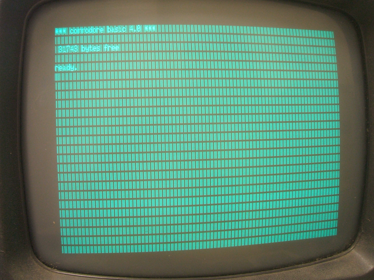
- Vertical lines on the screen: A more specific case is that of constant vertical lines all over the screen, in the same position for each character row. An example can be seen on this page. The specific problem could have been the character ROM or the shift register receiving the data from the character ROM. In this case it was the character ROM. Note that the vertical lines only show where characters should be, not the borders and even not in between the characters. That would be a different error. Thanks to Alasdair Macdonald for reporting this and providing the picture!
- Video board:
A comment by William Levak:
When you get to the video board, there were 2 capacitors on the original version of the video board for the original PET that went bad frequently.
- Monitor after reset: When the PET comes up with the built-in monitor (TIM) instead of the BASIC prompt, check the value of the stack pointer. If it is very low (e.g. "01") then there is a stack overflow, probably caused by too many interrupts. Check the "VDRIVE" signal on the keyboard PIA or VIA IC. If it shows the vertical sync video signal, only that it is not between 0V and 5V, but between around 0V and 1V, then the VIA may be broken and pulling the signal low, so that the PIA has problems detecting the interrupt.
- No 'chirp' after reset:
The 12" models have a piezo beeper and since BASIC4 they "chirp"
when reset. If such a model does not do this, check the
beeper signal. If it does not exist, there may be problems with the
VIA.
In my case I had the 8296 boot either with chirp into the TIM monitor or without chirp into the BASIC prompt, and I found a broken VIA. - SYNTAX ERROR on every command and screen scrolling problems: I read of a case where on every command entered the system reacted with a "SYNTAX ERROR". Also when scrolling the screen, some characters change. This is a problem when the main CPU reads the video screen. When a command is entered, it is read from screen, not from some buffer memory. Also when the screen is scrolled, the data is read from the screen and written back to it. So both problems came from the same source, the bus driver that separated the video RAM from the CPU bus. It had a broken driver in one of the lines.
- Blink codes
When being switched on, the drives perform a self test. When an error is found, a specific blink code is shown on the LED. On the link you find the error codes that give you hints what could be wrong with the drive. - Error channel:
Once the drive runs, you can check the error channel of the drive. If it works ok, it means that at least the DOS part of the drive and the communication with the computer seems to work - the FDC part may still be broken depending on the symptoms.
Also via the error channel you could perform some memory test yourself.
- Harddisk
The D9060 and D9090 use a similar disk operating system as the disk drives, but do not communicate directly to the drive but via a SASI (predecessor to SCSI) interface that then controlls an MFM drive.
See the link for more information on D9090 testing.
- 6540 ROM sockets
The original PET came with 6540 ROM chips. These are basically gone now. On the link you find an adapter to replace such a ROM with a 2716 EPROM . - 6550 RAM sockets
The original PET came with 6550 RAM chips. These are basically gone now. On the link you find an adapter to replace such a RAM with a 2114 SRAM . - 6540/6550 tester
Here is a tester for the RAM and ROM chips of an old PET. .
- Keyboard Repair Descriptions:
- ftp://www.zimmers.net/pub/cbm/documents/repair/keyboard.txt
- http://www.commodorecomputerclub.com/cleaning-a-pet-4032-keyboard/
- https://www.flickr.com/photos/afachat/sets/72157646409152698/
- http://www.bjtechserv.com/Magazine/C64/C64_Keyboard_Clean.htm
- http://www.6502.org/users/sjgray/projects/petkeyboard/index.html
- http://blog.tynemouthsoftware.co.uk/2014/09/commodore-pet-repair-part-8-keyboard.html
- https://www.youtube.com/watch?v=TwAu_seSt2A (for a C64, keyboard starts at 4:00)
- Power connector:
William Levak on the cbm-hackers mailing list reported intermittend power problems with the SuperPET. He fixed it temporarily by pressing on the connectors of the power cable that goes from the 6809 board to the main system board. When it went out completely, he found that the cable had been pulled out and he had to re-crimp it (stripping off a bit more insulation to get more bare wire to crimp).
- Classic Computing Forum
A collection of helpful documents for the repair of a PET. Note the forum is in German, but the documents usually are in English). - Vintage Computer Forum
Very(!) helpful people in this forum. - Diagnostic Manuals commodore.ca has a number of diagnostic manuals.
- Test and repair 9" monitor PETs A description how to repair 9" monitor PETs by Hugo Holden
- PET memory test program commodore.ca has memory test program for an 8k PET, which could probably be adapted for larger memory sizes.
- PET restoration: of an original PET 2001-8 by Dave Gostelow - 20100103 obviously gone. Only found in the web archive: http://web.archive.org/web/20091027142923/http://geocities.com/davegostelow/PETrestore/PETrestore.html.
- Larry's portcommodore 8-bit troubleshooting list
- Description of a PET repair
Interesting description to solve several problems with a non-working PET - Reparing a Japanese PET with a strange video problem:
The PET described here had (among other problems) a nasty video problem. Each screen character line increased the screen address only by 36 even though 40 characters were shown. This was finally lead back to the character clock being weak, and when the raster line started, it became even weaker so that the single actual pulse there was missed. This caused the counter to not overflow to 40 on the last character, and as the lowest two address bits were reset, the next line started at 36 (instead of 39 as you would expect by a missed clock pulse). The cause for the weak clock pulse finally was that the reset for the JK-flipflop that produced the pulse was too early. And the cause of this was the the NAND that produced the reset signal only used one input and did not obey the clock input. So the video pulse actually reset itself, thus becoming very short and weak.
The original web site seems gone, but there is the Vintage Computer Forum on that machine.
Disclaimer
Return to Homepage
Last modified: 2026-01-06