PET video architecture
(C) 2025-2026 André Fachat
The PET looks like a simple machine with almost the same features from the first machine to the last. But that is not the case. The main difference is in the video and memory section of the machine. So, in principle, there are three different architectures that need to be considered:
- The original with TTL-based, static timing video output. That includes the 2001 with static RAM, but goes up to all the 9" models with dynamic (main) memory.
- The 12" models with the CRTC, basically the Fat40 and the 8032 models
- The 8296 model that has 128kB of main RAM that is shared as video RAM as well
I have made a video series on all three types of models, explaining the system architecture and video output architecture. On this page I put the main info, and link to the videos.
- 2026-01-05 Started this page
Table of content
This section covers two sub-types of models:
- The original 2001 model with 1 MHz video RAM, prone to the famous "snow" appearing on the screen while the CPU accesses video memory
- The later 2001 or 30xx models in Europe that have 2 MHz video RAM, that allows time-sharing the video RAM with the CPU
The main difference in the system architecture for those two is a buffer in the later models, that holds the video data while the CPU is accessing the video RAM, so I'll describe them here.
Explaining the Original Video Architecture
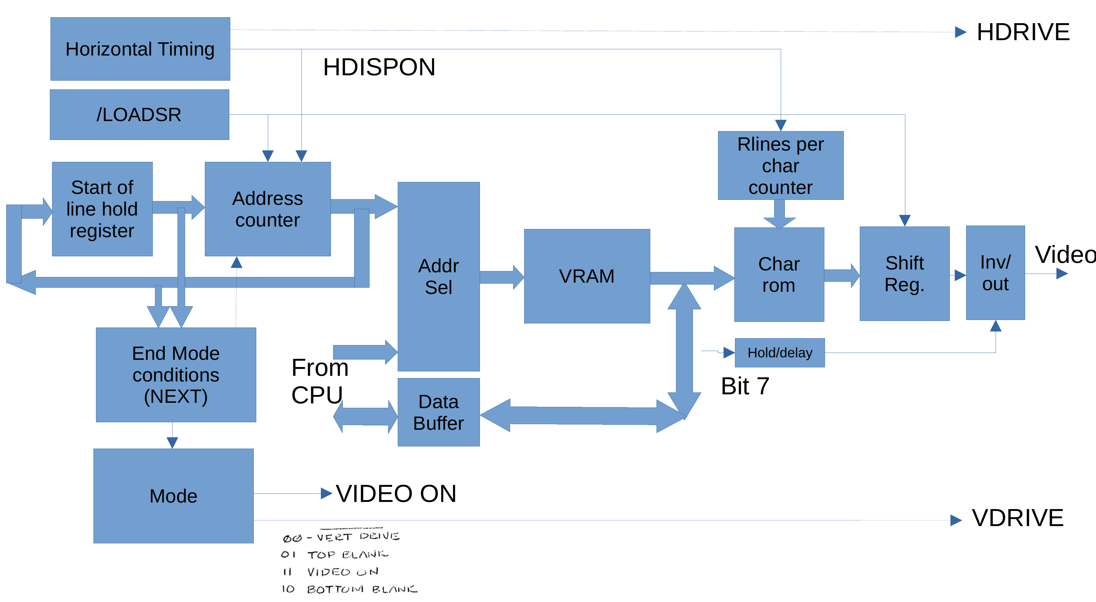
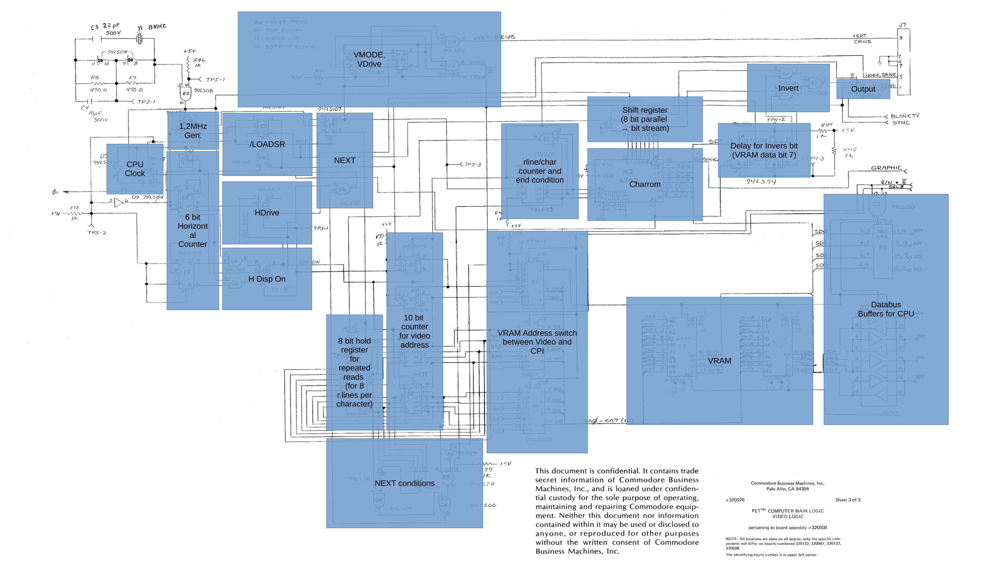
The original architecture created a static signal timing using TTL logic chips, derived from the 16 MHz system clock. The timing is divided into four modes, which relate to
- 00 - Vertical Drive: VSync
- 01 - Top Blank: between vertical sync and start of display
- 10 - VIDEO ON: display the video data
- 11 - Bottom Blank: between Video data and VSync
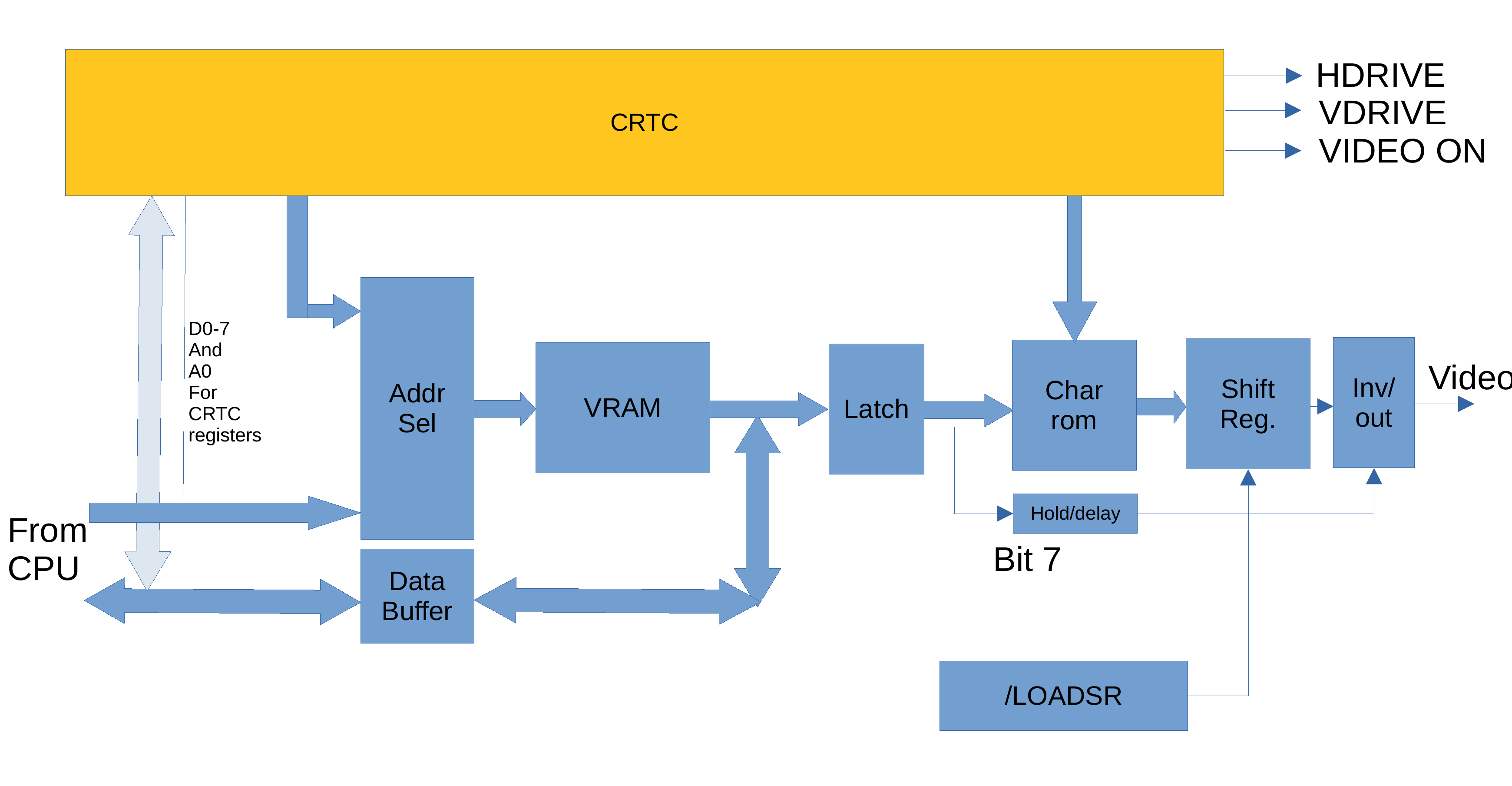
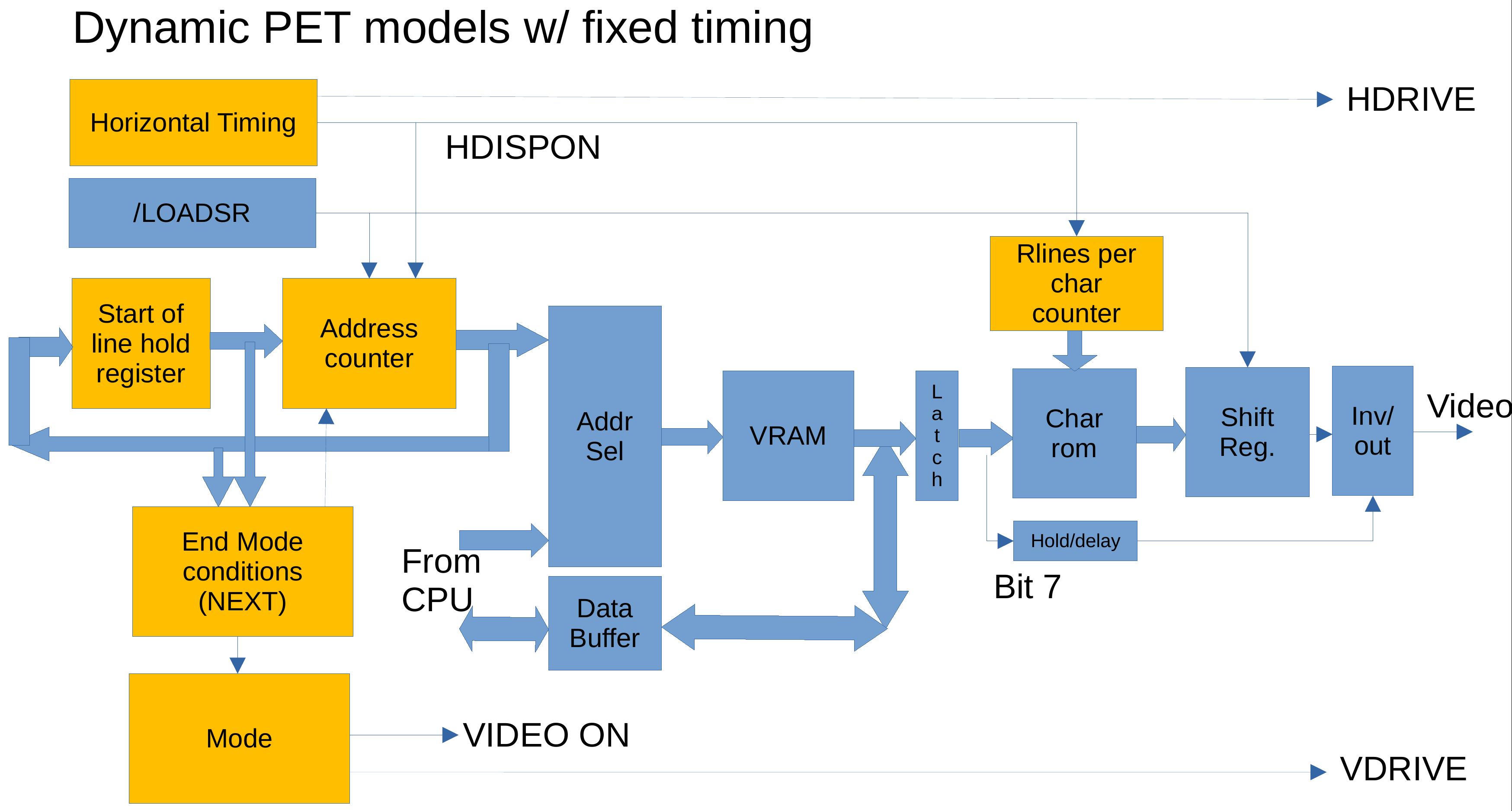
The address counter is used in all modes - it is loaded at the start of each line (not just when displaying data, but also in the other modes), and reloaded after the line ended (except when a new line starts). Conveniently, the length of the line is 64 cycles, which is a power of two. So, address bits above the first six bits can be used to determine the actual raster row. The NEXT condition then checks the address counter upper bits - the raster row - if the next mode should start. It does this depending on the mode, so each mode can have different lengths. In the PET, all modes have the same length of 20 raster lines except the active video output, which has 200 raster lines (which you would expect from 25 character lines of 8 bits).
The address counter goes to video RAM by means of a selector that switches between the CPU and video addresses. The video RAM output goes to the character ROM - here a buffer is included in the 3032 models without snow. From the character ROM the data goes to the shift register, and from there to the video inverter.
For more information see the linked presentation from the video below.
Video on the Original Video Architecture
This section covers the standard (up to 32k RAM) models with the CRTC for video timing:
- The 4032 so-called "Fat40", i.e. the 4032 models with the 12" screen
- The 8032 with the 12" screen, both fixed and swivel
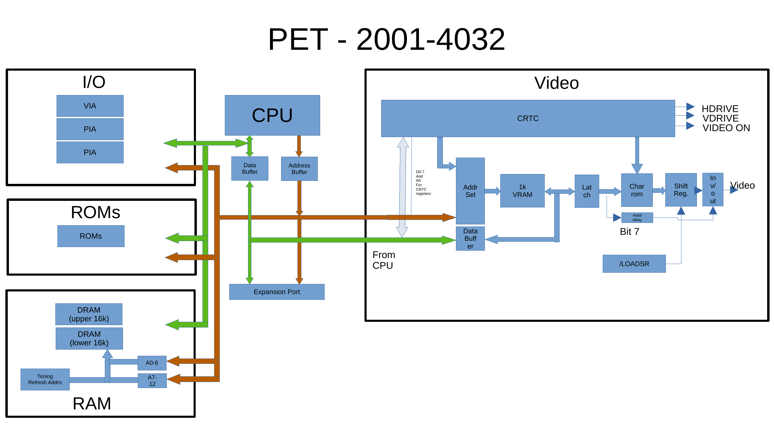
Explaining the CRTC Video Architecture
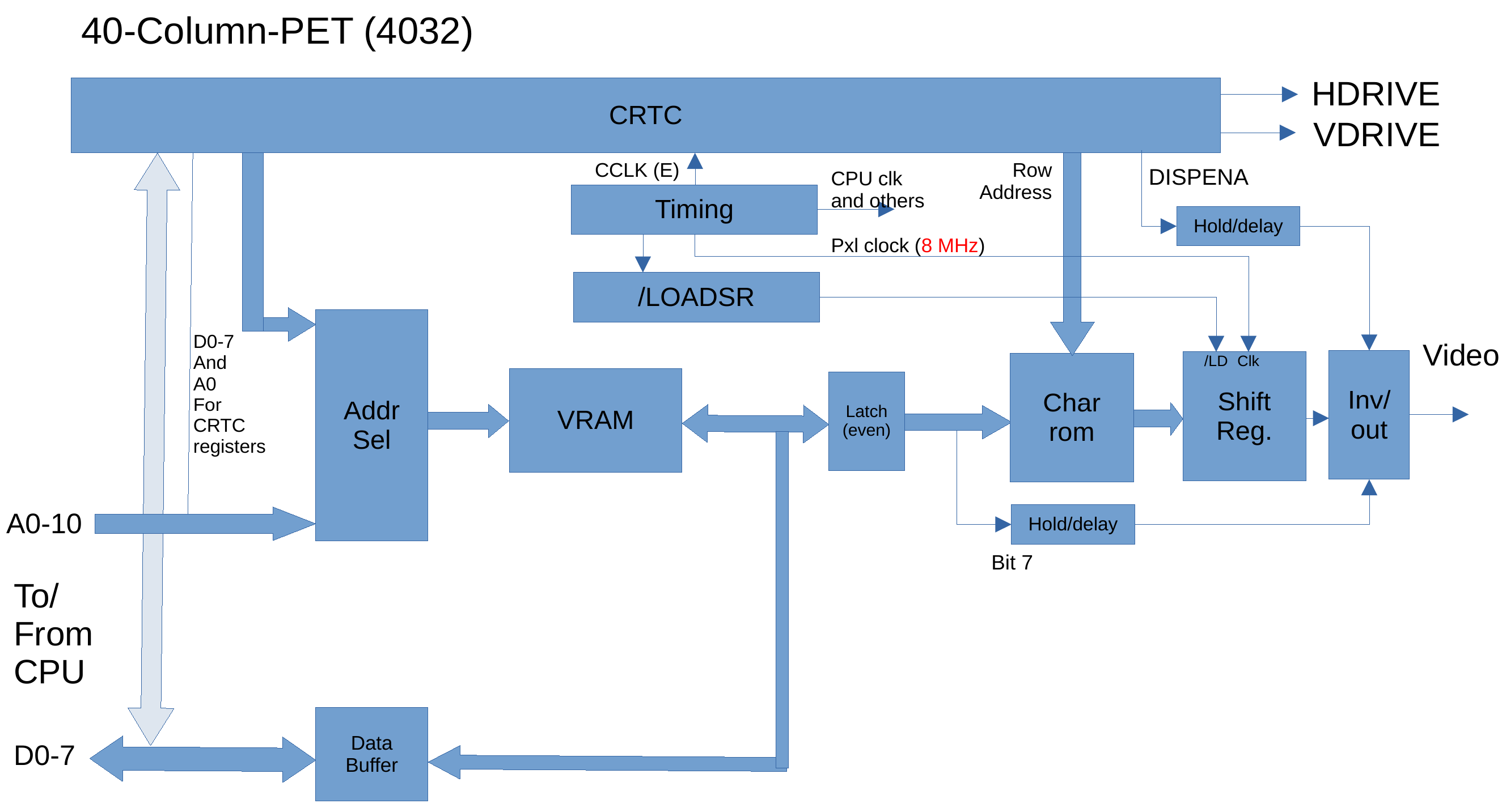
The CRTC models replace basically the whole static timing calculation by the CRTC chip. It creates the sync signals, the video memory addresses, as well as row addresses.
The rest of the video pipeline more or less stays the same: the address selector so the RAM can be accessed by the CPU and the video, video data latch(es), character ROM, shift register, and inverter.
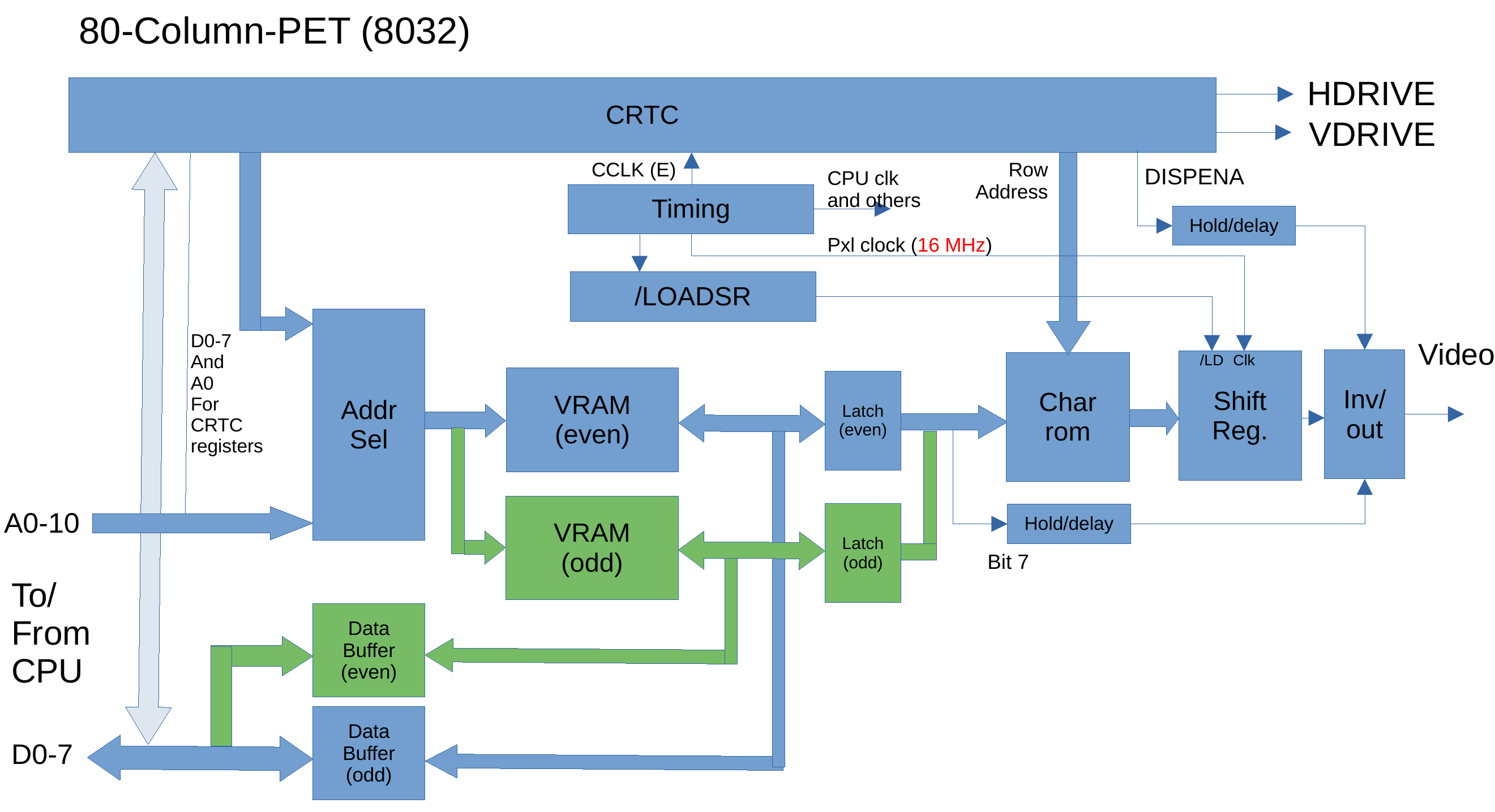
One interesting thing on the 8032 is that is uses a 16 bit video data bus ... yes, the video circuit reads two bytes at the same time from two set of video RAM chips. This allows using the same speed of RAM in the 40 column as in the 80 column models. A second latch stores the second byte until it is needed. You can see the parts marked in green in the diagram below.
This architecture is also the reason the CRTC is programmed to display 40 character even in 80 column machines - each character slot for the CRTC reads two characters from memory, to get to the 80 displayed characters in total.
Also note that the CRTC allows to set the timing and character height, number of displayed characters per line or displayed lines rather freely. This can and has been used for new demos. The issue with the 4032/8032 here is the restricted amount of video memory available, which is 1k resp. 2k. So, this has been more exploited in the 8296 models (see below). A glimpse of what can be done I have shown in the PET CRTC page
For more information see the linked presentation from the video below.
Video on the CRTC Video Architecture
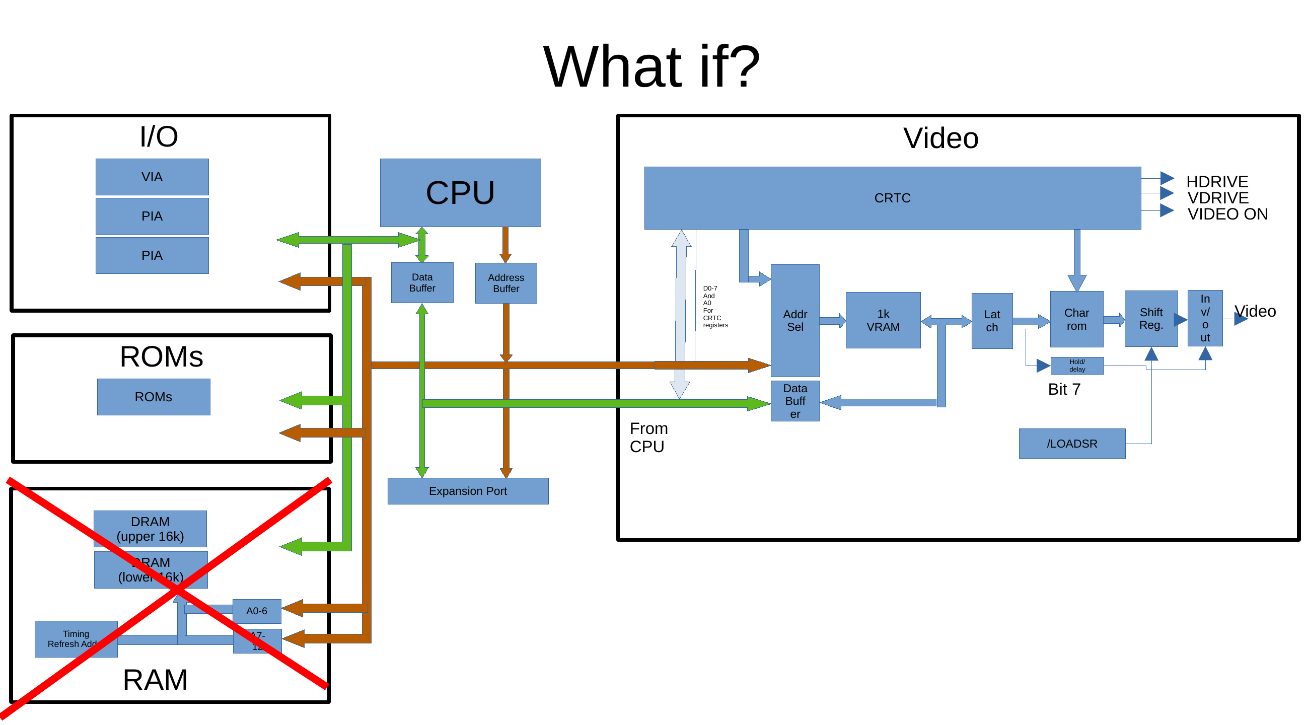
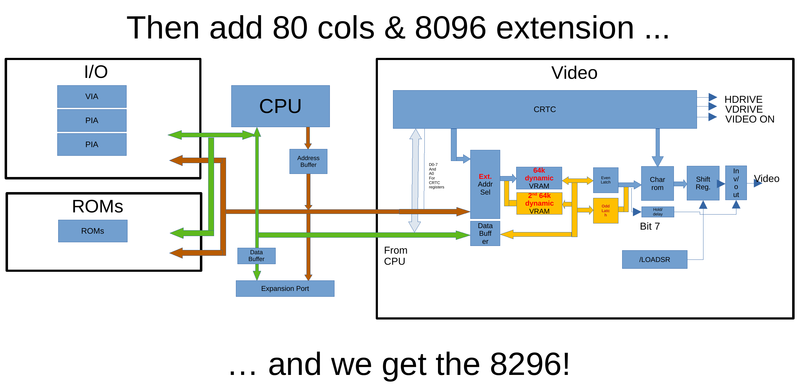
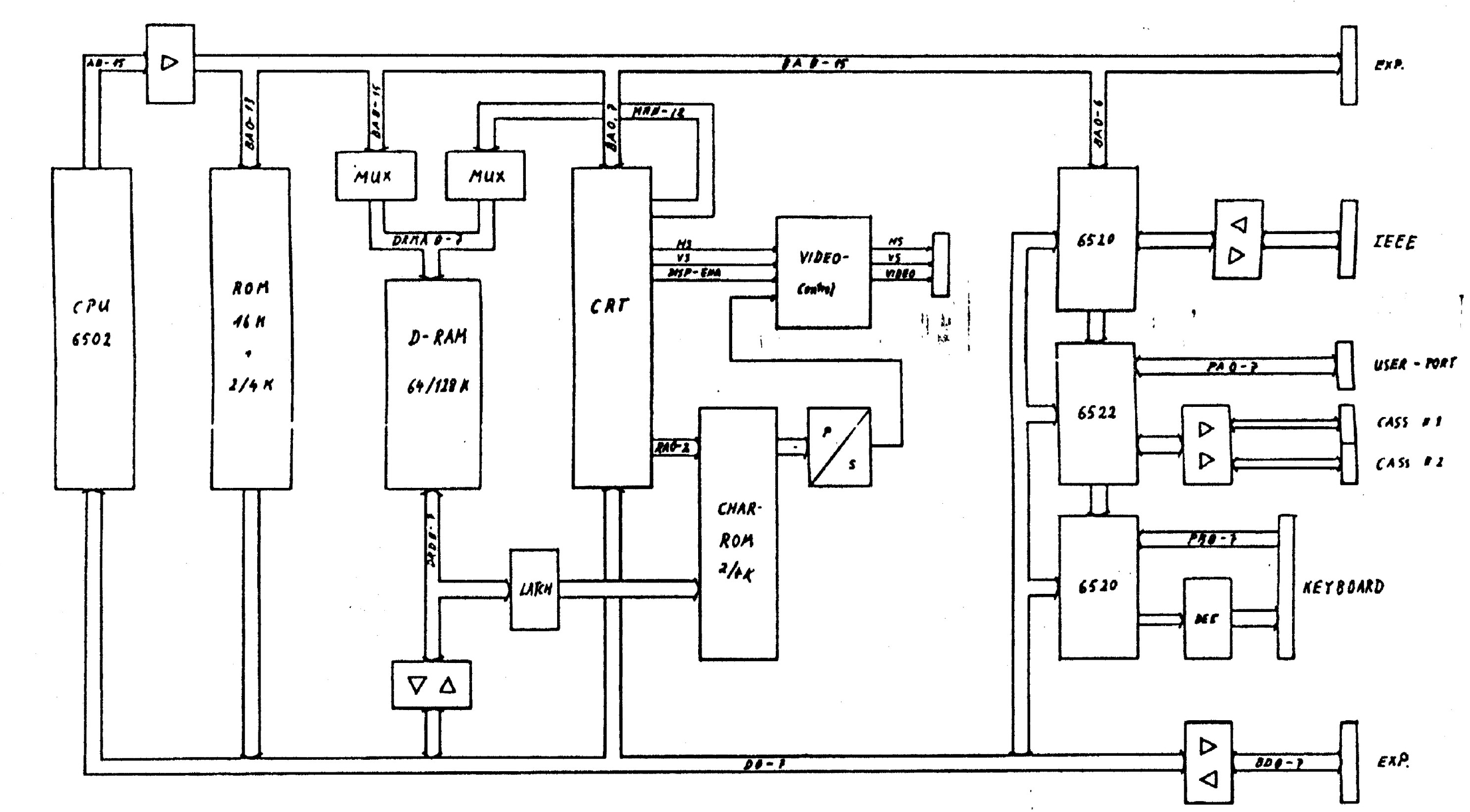
The 8296 was a re-design of the PET, using 2 banks of 64kB of dynamic RAM, for a max total of 128k RAM (of which 96k were easily usable, and some of the rest were used for the video). The PCB was made configurable, so it could be used as 4032, 8032, or even as a 4096 model, but I don't know of any such model besides the 8296.
Explaining the 8296 Architecture
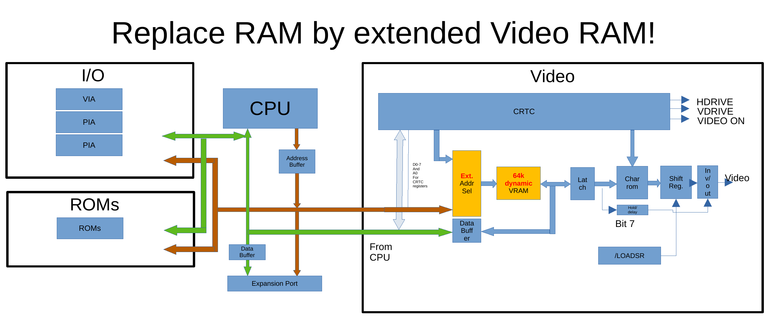
The main architecture changed significantly, as the main memory was now also used for the video. Basically what Commodore did was, they replaced the main memory of the older machines with a greatly extended video RAM.
One other change is they used a single 8 bit video data bus instead of the two byte (16 bit) data access path of the 8032. This way they were able to further reduce the chip count, but it required faster RAM.
One could have speculated that adding a second bank is required to get to 80 columns, similar to the 8032 CRTC models. However, the video RAM is completely in the first memory bank. This allows to leave out the 2nd bank altogether to use the board as a 4032 option. This is probably also a reason for using faster RAM and allowing only a single 8bit video data path.
As Commodore was using a PLA to generate the timing, they were easily able to use page mode read cycles from the single video bank to speed up the RAM access. Dynamic RAM gets the address in two chunks, first the page then the byte in the page (page here meaning a memory block that requires just half the number of address bits, so is 256 bytes for a 64k chip here, but could be 128 bytes for a 16k chip here). Page mode read allows sending the page once, then sending different byte addresses without page address to access differenty bytes in the same page.
The 8296 has the flexible timing of the CRTC, but also the CRTC is able to address 8k of video memory in total (where 4k can be read and written by the CPU, the second 4k can only be written to). This, together with the flexible timing, allows to create interesting demo effects as can be seen in the video linked below.
For more information see the linked presentation from the video below.
Video on the CRTC Video Architecture
Return to Homepage
Last modified: 2026-01-06