Roll your own PET4032 (Fat40)
(C) 2006-2006 André Fachat
This page describes how you can build your own PET 4032 using the boards of the CS/A65 computer.
Well, not actually the whole computer, but at least the mainboard, where "only" the case, screen, and power supply are missing. I have though managed to use a standard PAL screen with this PET by redefining the timing values the PET ROM writes into the CRTC registers.
Basically what you do is to combine the PETCPU, PETIO and Video boards into one computer, put the PET ROM into a ROM for the PETCPU ROM socket and there you are. The following sections describe the special settings on the different boards.
- 2010-05-11 Added beta version of patched PET BASIC4 ROM to run on CS/A in 2MHz
- 2006-12-22 Added the version using the CPU and BIOS boards instead of the PETCPU board ("Caspaer" setup).
- 2006-11-12 Added the ROMs.
Table of content
Fat40 Setup
 This section describes a setup using the three PETCPU, PETIO
and VDC boards.
This section describes a setup using the three PETCPU, PETIO
and VDC boards.
- Board Settings
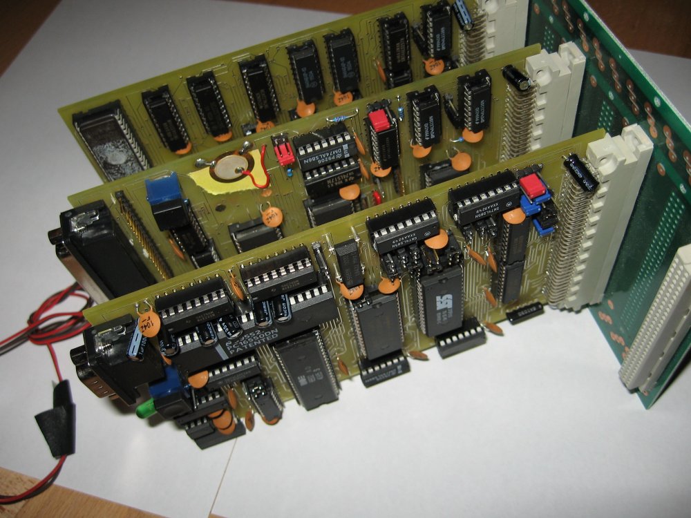
This section describe the CS/A65 boards making up the PET 4032. Here is a picture of the three boards on a backplane. Note the separate cable between the VDC and the PETIO boards, to handle the video retrace (VSYNC) interrupt generation from VDC to PETIO and the character ROM selection. from PETIO to VDC.
- PETCPU board
The PETCPU board must be set to a maximum of 32k RAM on the board
itself, and maximum of 28k of ROM, so that the memory area at
$8*** is selected on the CS/A65 bus and can be handled by the
video board. Actually all memory not handled by the PETCPU is
covered by RAM from the video board (e.g. the $9*** area).
To achieve this, the PETCPU board must be set to use the
$01**** are on the bus. In addition it must exclusive-or
the address lines 15 and 12 - as the PET CRTC is set to a
memory address of $9000 - but the video board resets the video
to $0000 with the control register and the values set in the
CRTC. Also the I/O area must be enabled for $E800 to $EFFF.
You can see the jumpers in this picture. Please note that this is jumpered for 2MHz, and the RAM is missing - as the RAM is setup to be used from the video board. - PETIO board On the PETIO board only the "special features" must be switched off, especially the IEEE488 slave mode feature, as the ROM does not handle this, as well as the EOI must be located at its original place on the keyboard PIA.
- Video board The video board must be set to the memory area $01****. Otherwise it should best be a 1.4 version, as the control port is reset with /RES and needs not be set by the ROM.
- PETCPU board
The PETCPU board must be set to a maximum of 32k RAM on the board
itself, and maximum of 28k of ROM, so that the memory area at
$8*** is selected on the CS/A65 bus and can be handled by the
video board. Actually all memory not handled by the PETCPU is
covered by RAM from the video board (e.g. the $9*** area).
To achieve this, the PETCPU board must be set to use the
$01**** are on the bus. In addition it must exclusive-or
the address lines 15 and 12 - as the PET CRTC is set to a
memory address of $9000 - but the video board resets the video
to $0000 with the control register and the values set in the
CRTC. Also the I/O area must be enabled for $E800 to $EFFF.
- ROMs
In this section you can find the ROMs for the PET. They basically are the original PET ROMs, only that I have modified the CRTC timing parameters. Please note that the 2MHz (8032) version is experimental only, as the IEEE488 timing seems to be flakey now.
- Fat40 4032 graphics keyboard 1MHz This is the 1MHz ROM that produces roughly PAL compatible video output.
- 8032 business keyboard 2MHz This 2MHz version is experimental. As the VDC board can only do 80 columns with 2MHz bus frequency, no 8032 with 1MHz is possible.
Caspaer Setup
- Board Settings
This section describe the CS/A65 boards making up the PET 4032 in a setup with the CPU+BIOS board combination. Please note that the separate cable between the VDC and the PETIO boards, to handle the video retrace (VSYNC) interrupt generation is still required as above.
- CSACPU board The CPU board must be set to 1MHz. The ROM patch below expects the MMU at $eff*, so the board must be set to an I/O area of 2k from $E800-$EFFF and the MMU to $EFF*. By modifying the patch other values are possible.
- BIOS board The BIOS must be set that the ROM as described below is found at $08000-$0FFFF so that the CPU boots from it. The RAM should be on $00000-$07FFF.
- PETIO and VDC boards: Please use the same settings as described above.
- ROMs
The ROMs are basically the same ROMs as above, i.e. including the modified CRTC timing parameters. In addition, the CPU must set the MMU and BIOS board to correct values on Reset. This is done by a small patch that is included in the ROM listed below.
Unfortunately the IEEE488 interface - despite its timing-resistance - does not - as it comes with the PET - work at higher speeds than 1MHz CPU clock. I have now also patched the ROM to work in the Caspaer setup with 2MHz.
- Fat40 4032 graphics keyboard 1MHz This is the 1MHz ROM that produces roughly PAL compatible video output in the MMU version.
- Fat40 4032 graphics keyboard 1MHz @MON This is the same ROM as above, only that it includes a PET version of the @MON machine language monitor at $A000, to start with "SYS 40960".
- Fat40 8032 graphics keyboard 2MHz @MON This is the same ROM as above, with the patched IEEE488 and video timing to run at 2MHz.
- ROM diff This is the ROM diff as hex dump. The Reset vector is modified to point to the patch that sets up the correct values and jumps to the old reset routine.
- Patch source This is the source for the ROM patch (excluding the modified reset vector.
- IEEE488 patch: This is the IEEE488 patch that makes the IEEE488 work at 2Mhz (beta).
	*=$f0d8
	jsr $fe20

        *=$fe20
        lda #4
l1      sec
        sbc #1
        bne l1
        lda $e840
        rts
Disclaimer
Return to Homepage
Last modified: 2010-05-11