CS/A65 PETIO
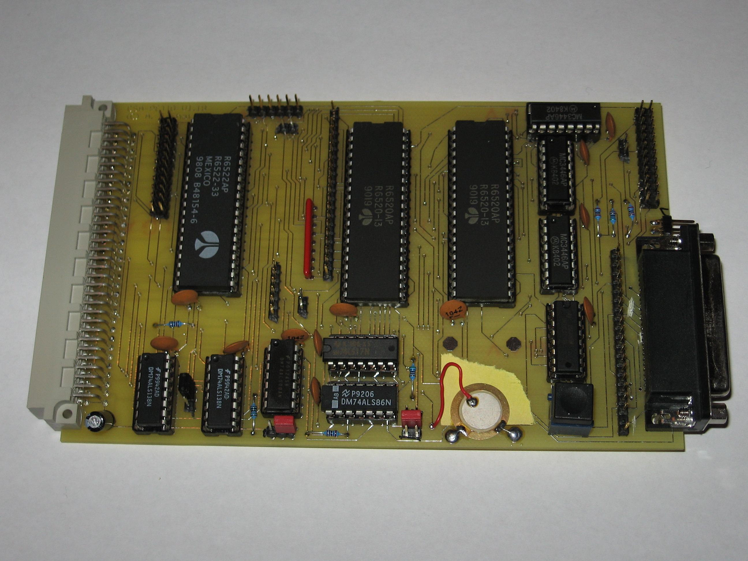
This board implements Commodore PET compatible
I/O interfaces. This includes the keyboard, IEEE488,
userport (mostly) and tape ports. It adds the functionality
that the IEEE488 bus can also be used as a device.
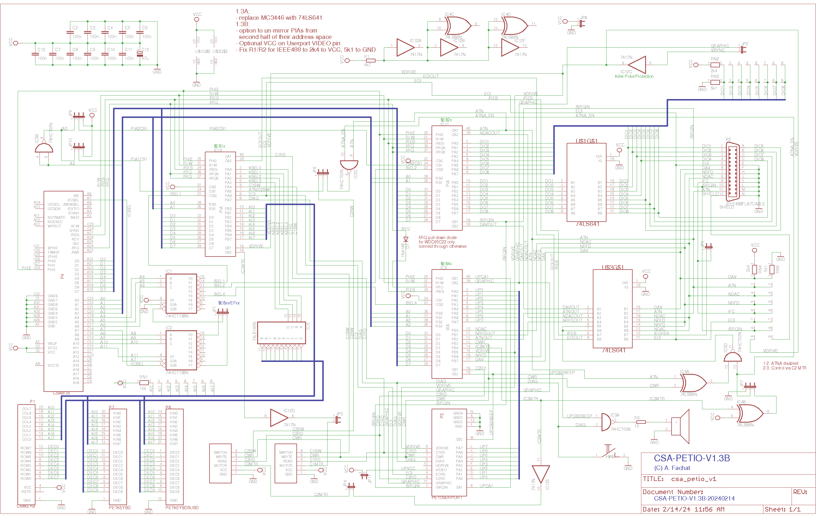
- 20240215 Added version 1.3B that corrects IEEE488 term resistors, opts to block only 8 addresses for each PIA instead of 16.
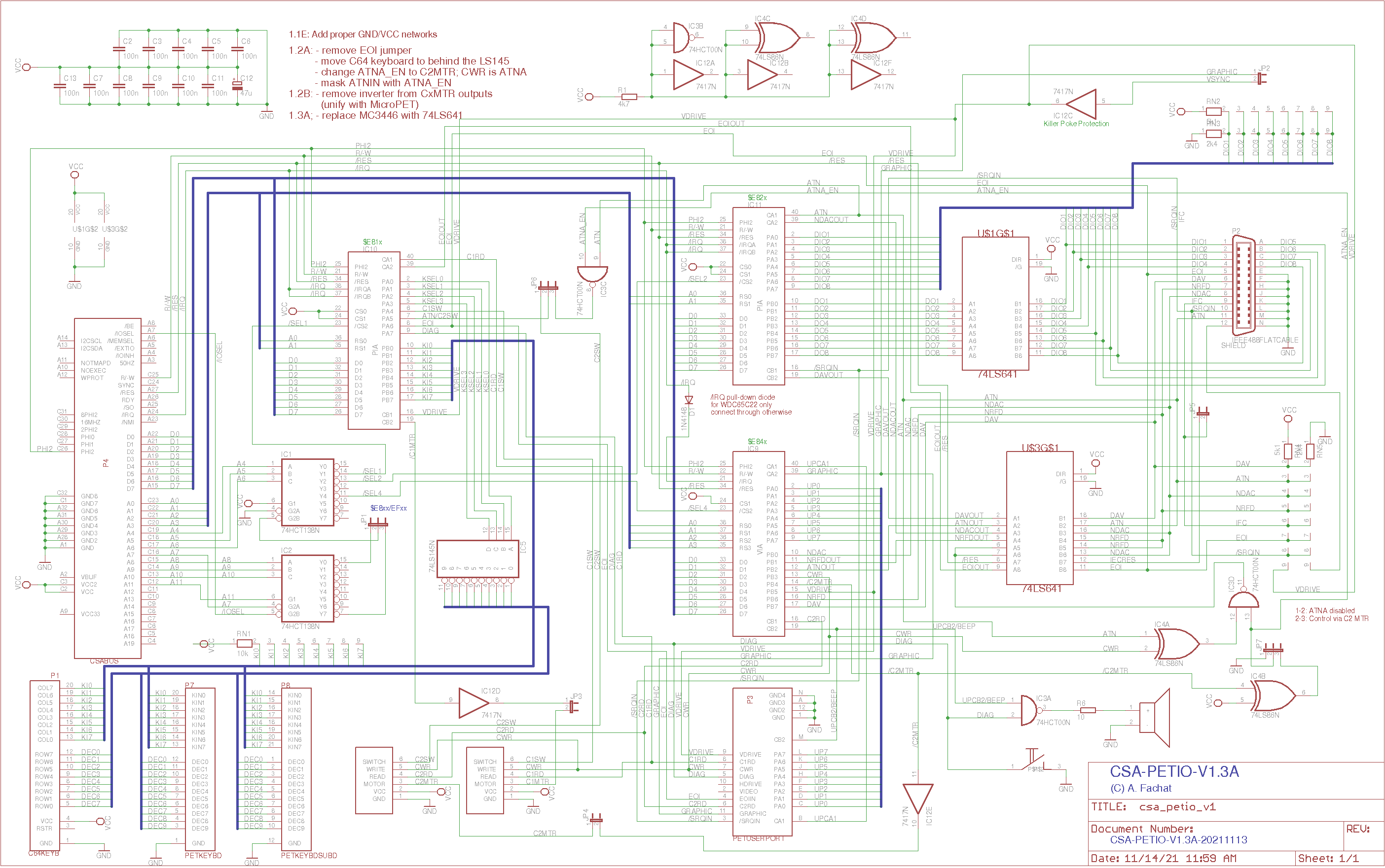
- 20220313 Added version 1.3A that uses 74LS641-1 instead of MC3446 (untested)
- 20211121 Added version 1.2B that can finally work as a drive for other PETs again.
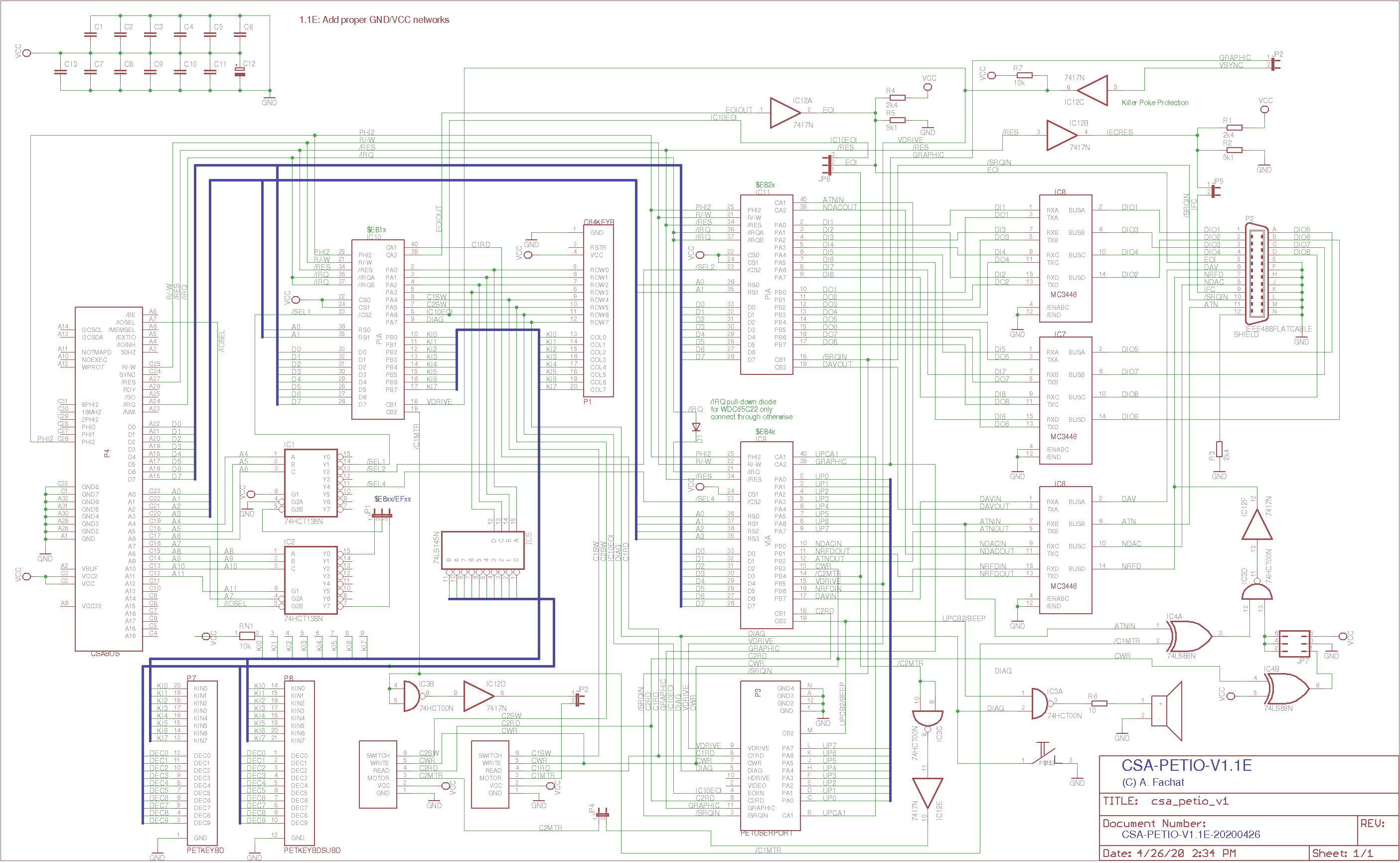
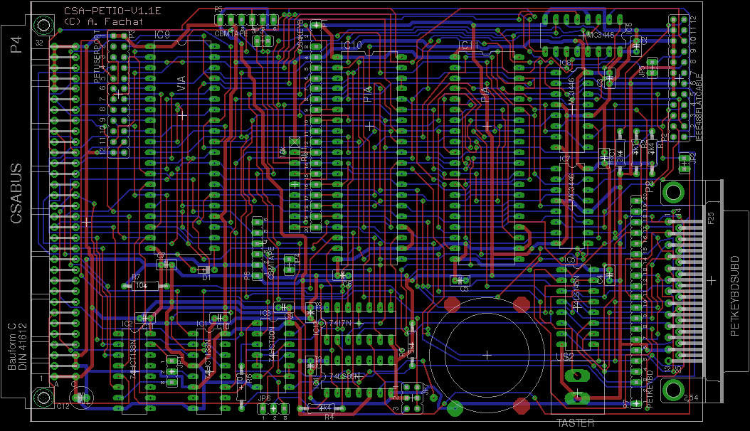
- 20211018 Added version 1.1E
Table of content
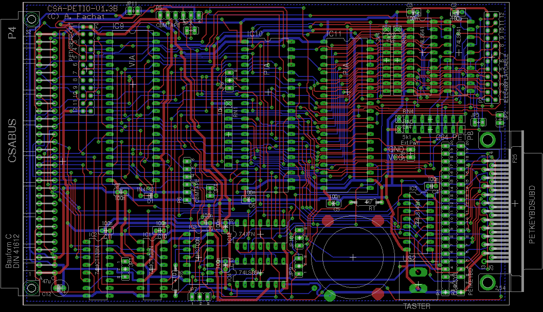
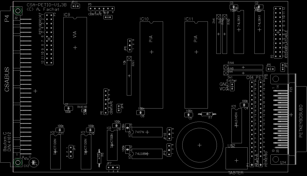
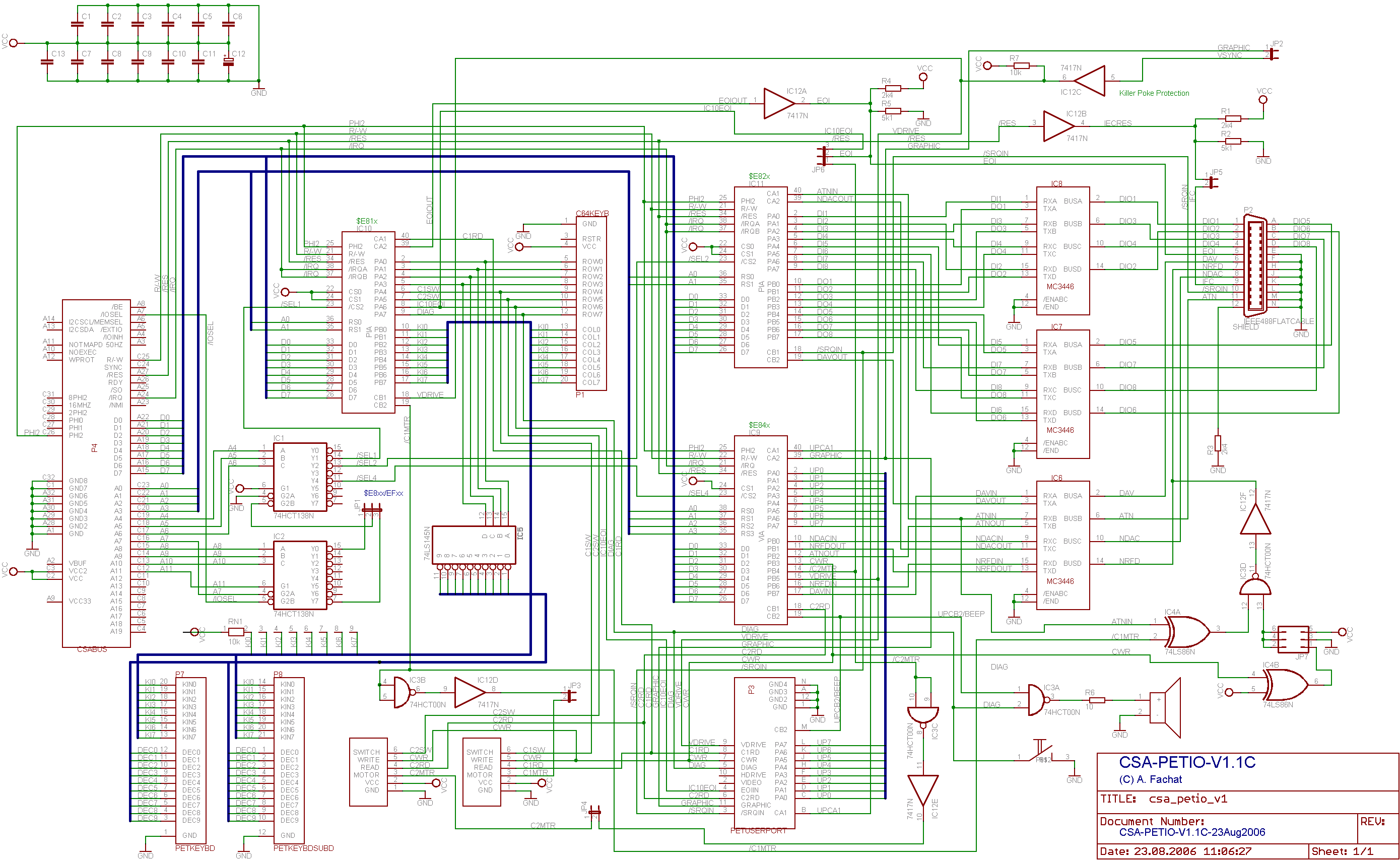
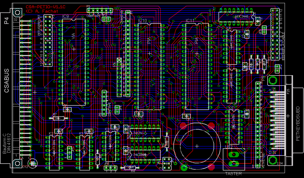
Version: 1.3B
Status: ok
Notes
| This board has been tested as patched 1.3A only so far | |
| The PDF layout file contains the description of the jumper settings. |
Version: 1.3A
Status: ok (with IEEE488 pullups only)
Notes
| This board works, only the IEEE488 termination resistors should be populated as pullup only (the 2.4k pulldown is wrong). This is fixed in V1.3B. |
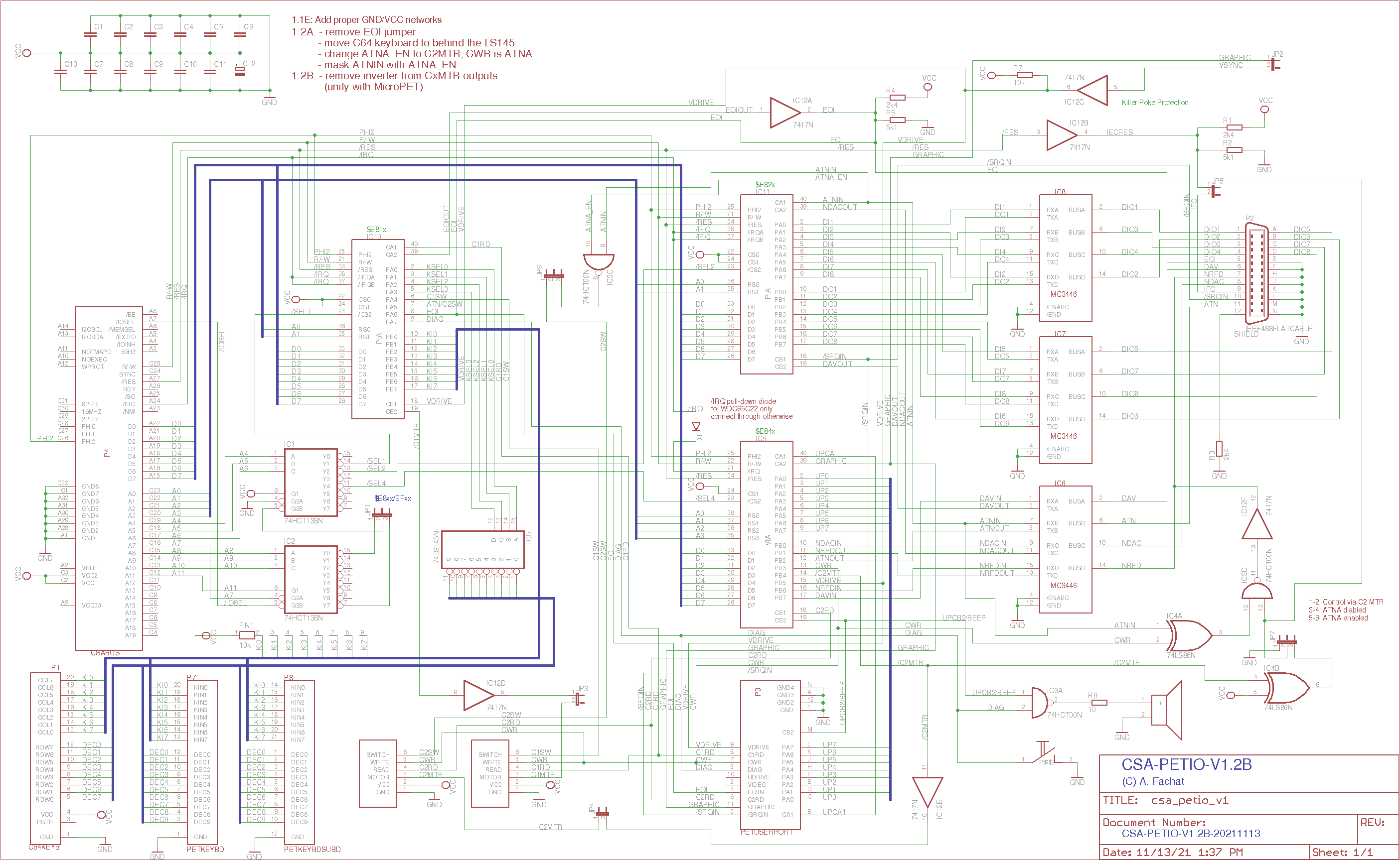
Version: 1.2B
Status: untested
Notes
| The schematics has been tested, now the board can work as a drive for other PETs. |
Version: 1.1E
Status: untested
Notes
| The layout has been overhauled to include better power supply and ground networks. |
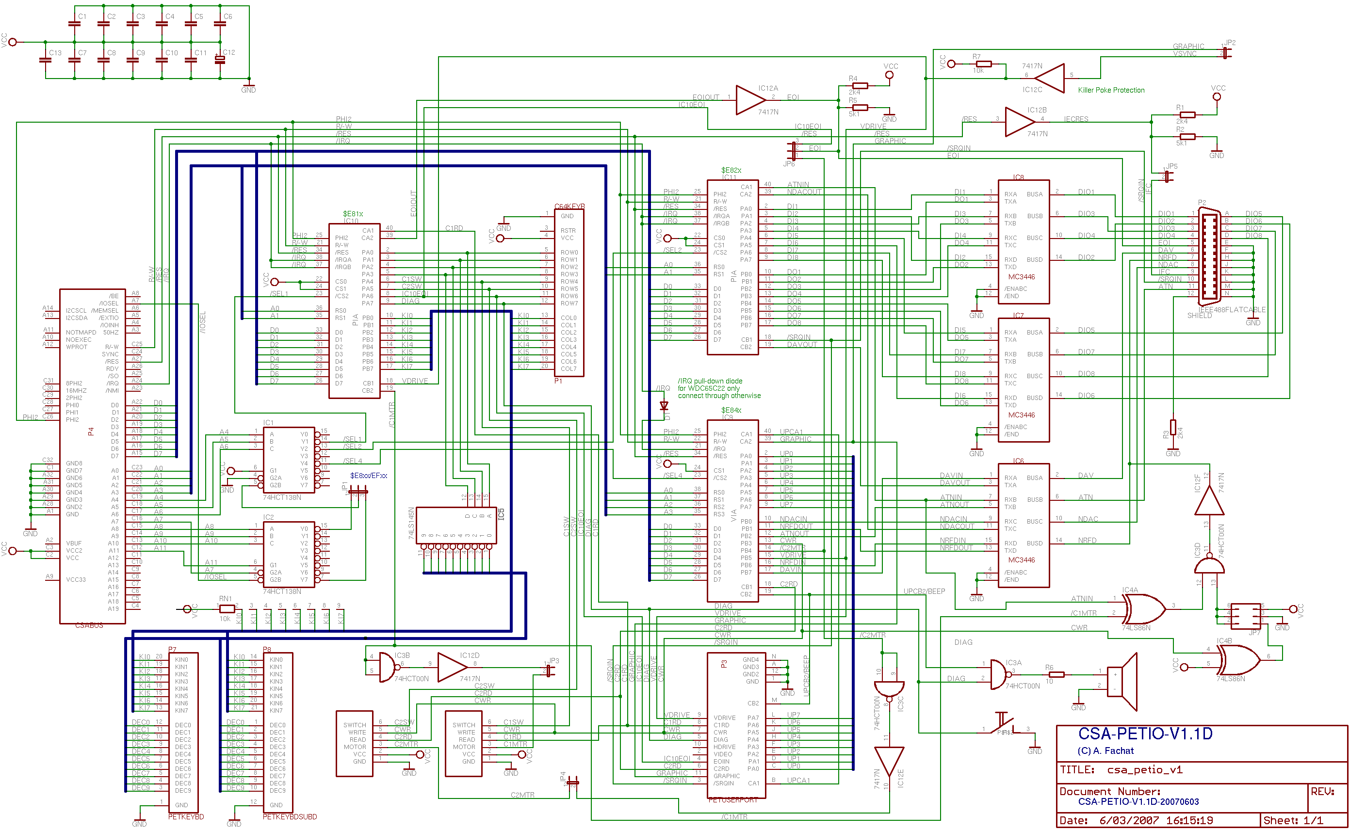
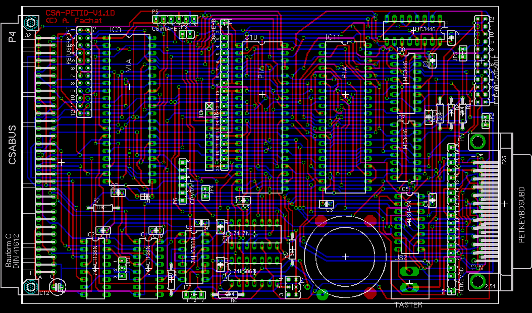
Version: 1.1D
Status: untested
Notes
| This board has an additional diode (e.g. 1N4148) to accomodate for the WDC65SC22's totem-pole /IRQ output, as opposed to the orginal's open-collector output. Additionally it clears the board area under the piezo beeper. |
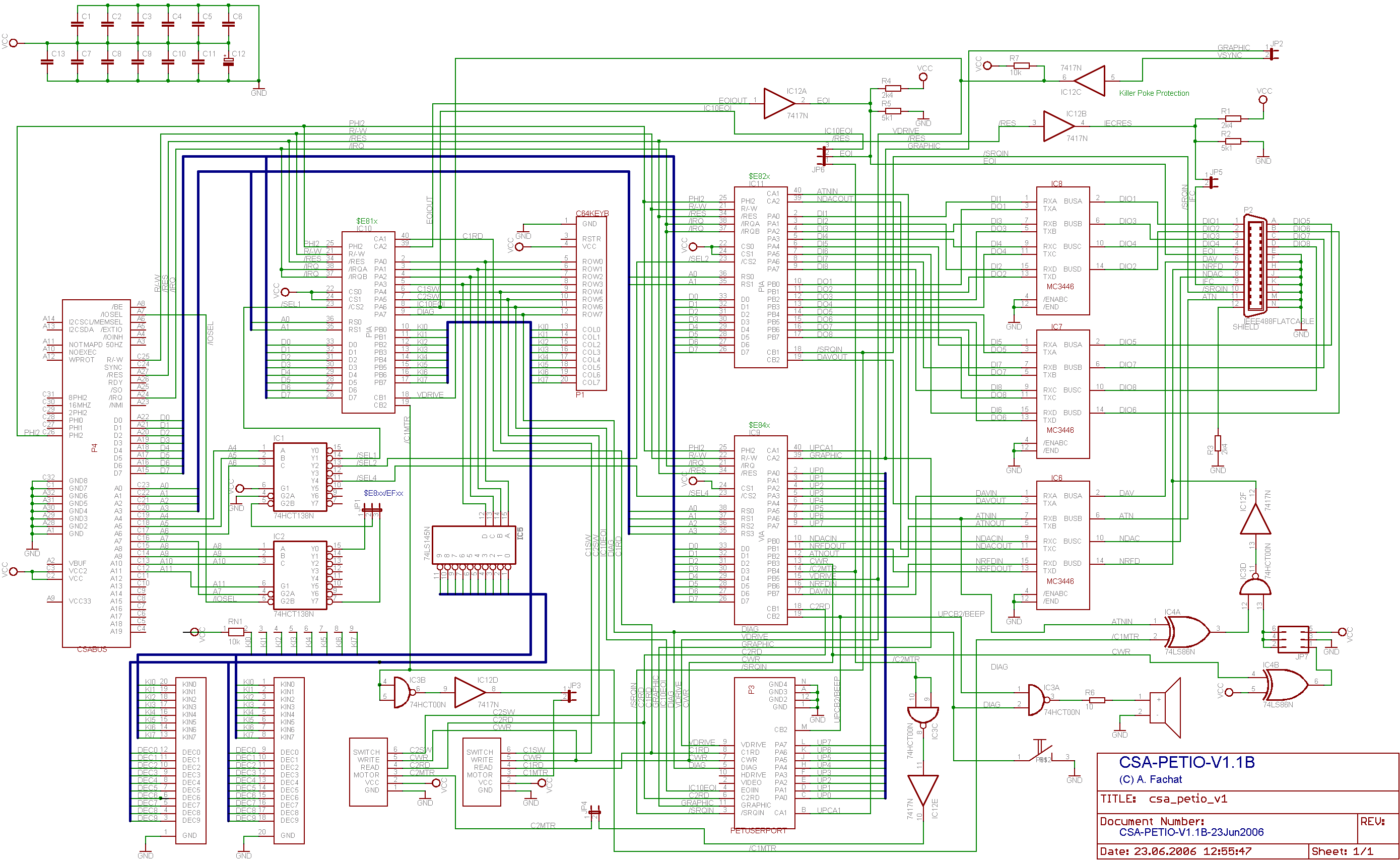
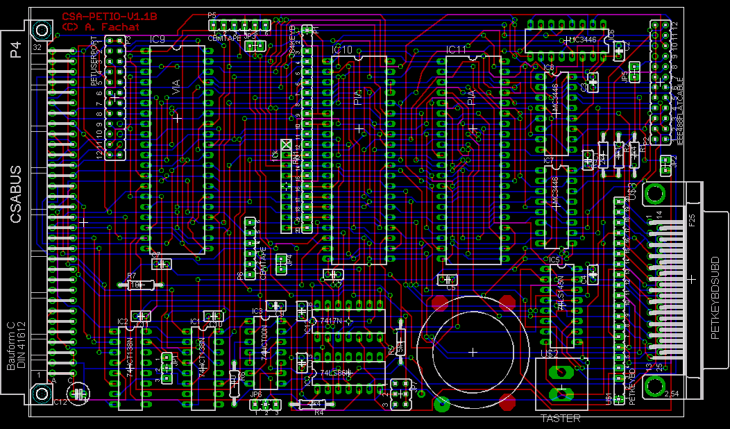
Version: 1.1B
Status: prototype with bug
Notes
| This board has been tested with a Commodore PET ROM. | |
| The 25-pin D-Sub keyboard connector has the wrong keyboard layout. Silly me, relying on the Commodore documentation, in this case the 8296 addendum to the 8032 manual - it has the wrong pinout listed. | |
| The use of the IEEE488 interface as device, not controller has not been tested yet. | |
| I did not really find a fitting piezo beeper device in the Eagle(tm) libraries, so please make sure you do not make short circuits. Best is to isolate the beeper from the board. |