Commodore PET <-> CS/A65 bus adapter
This is the description of an adapter to use CS/A boards in a Commodore PET. A lot of CS/A boards, including a video card, serial interfaces, floppy controller and an SCSI card can be found on the CS/A65 homepage.
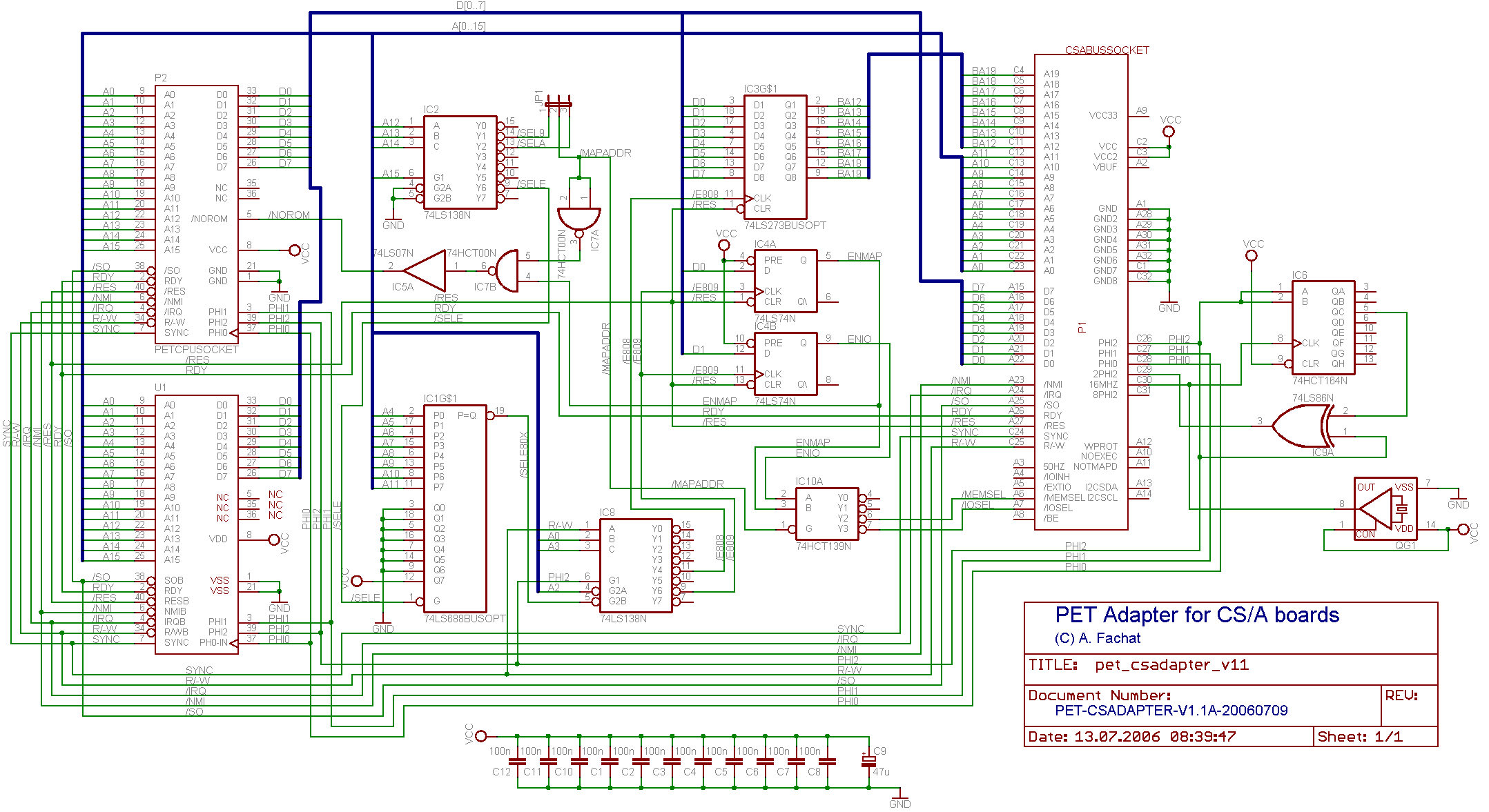
The interface itself is, in fact, pretty simple. It is a board that is plugged underneath the 6502 CPU of the PET. On the other side it provides a socket for a CS/A bus card. Two things have to be considered for the schematics:
- The PET only has two free memory areas, $9*** and $A***, so additional memory address lines have to be generated separately.
- The I/O area is pretty cramped. Especially when you look at the original I/O area address decoding: PIA1 is selected when A4 is high, PIA2 when A5 is high, VIA when A6 is high and CRTC when A7 is high - which means that on some addresses multiple chips are selected. Only $E80* is left open. So this area is used to map the control registers.
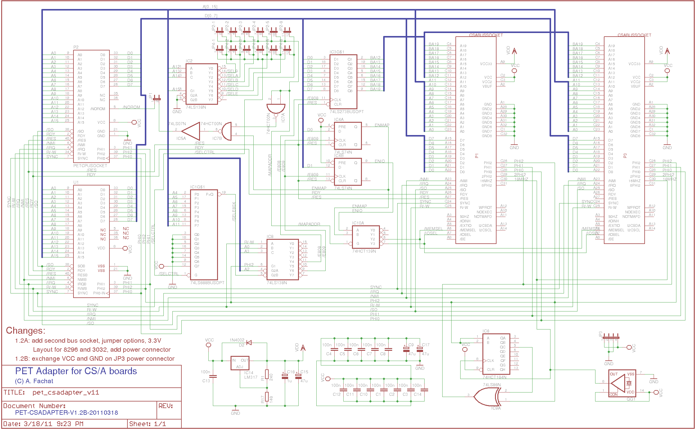
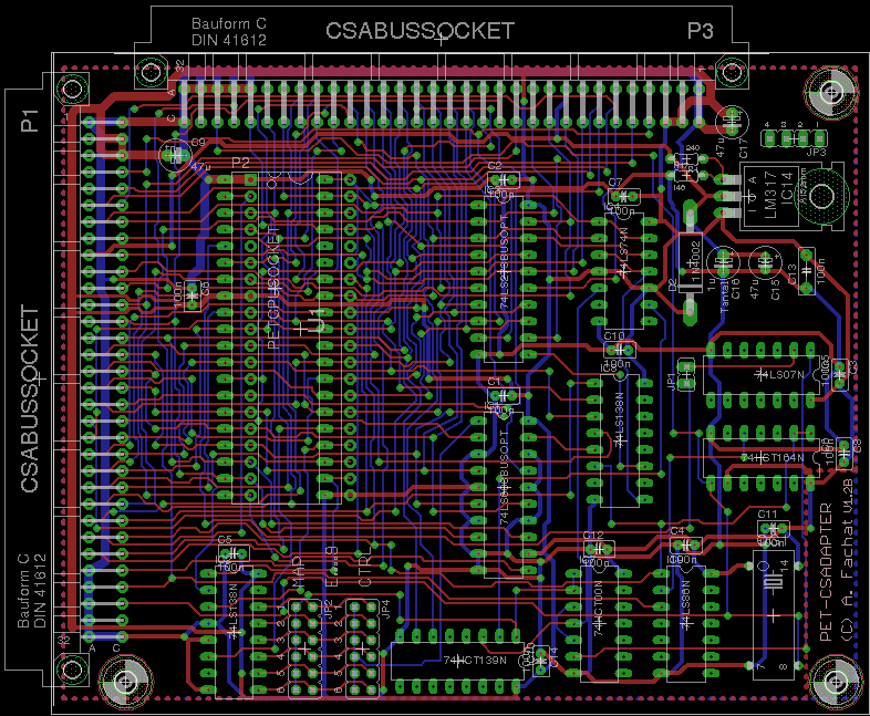
- 2011-03-18 Added the 1.2B version.
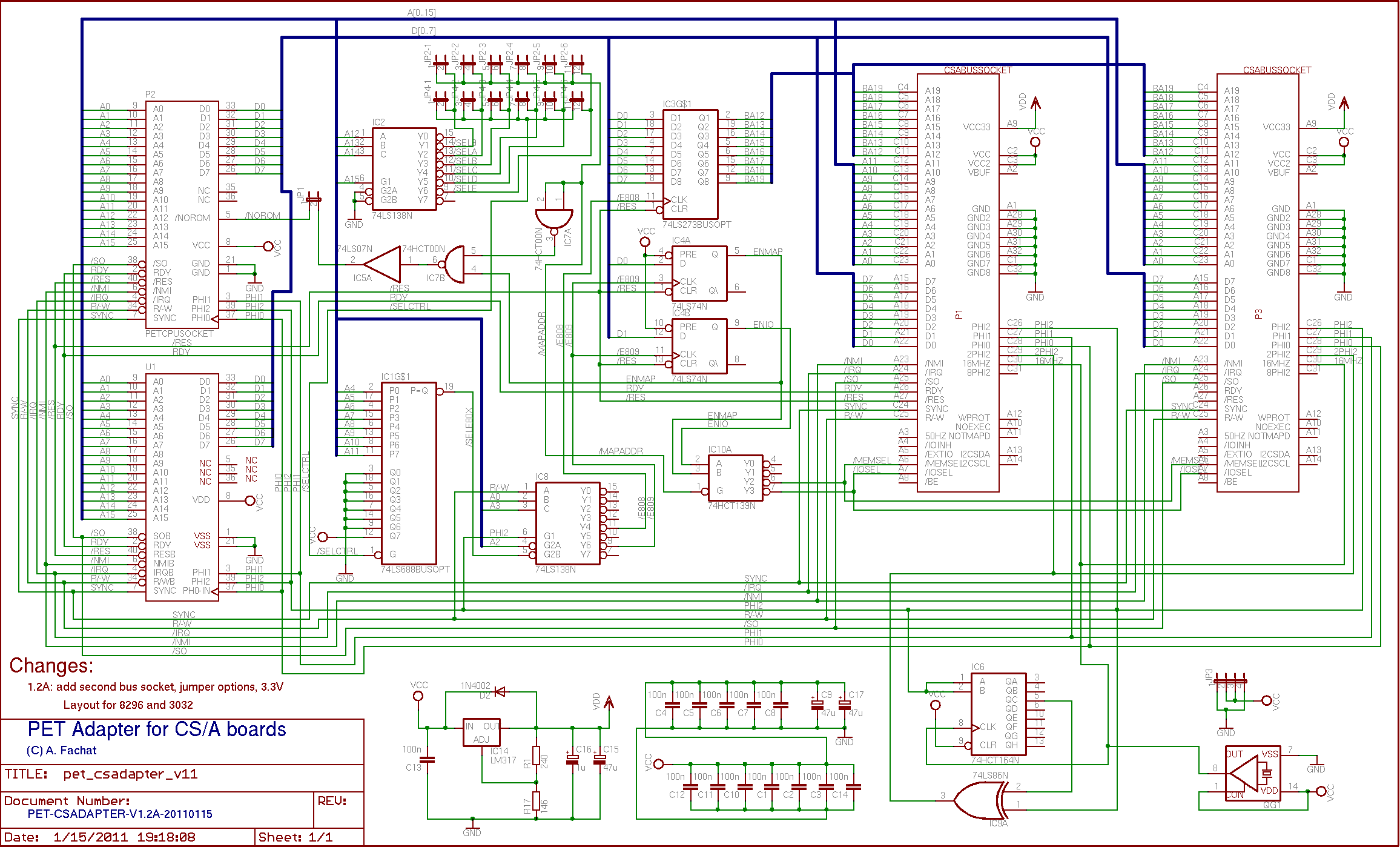
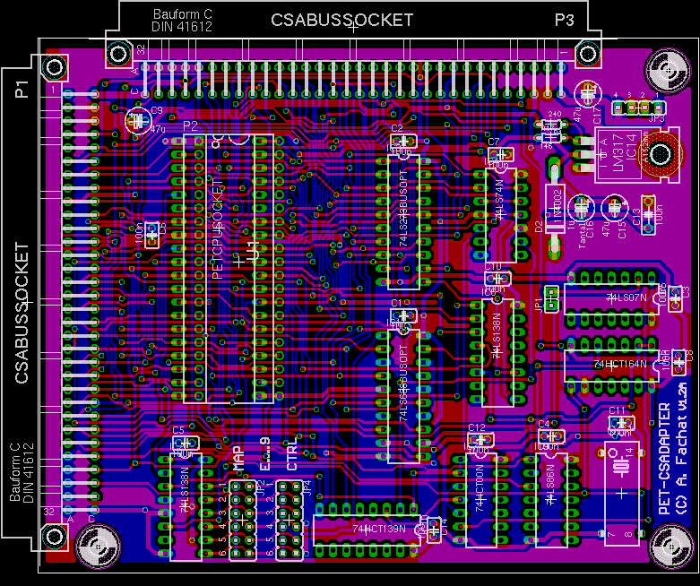
- 2011-01-15 Added the 1.2A version.
- 2011-01-13 Added the usage section
- 2006-12-20 Published the board.
Table of content
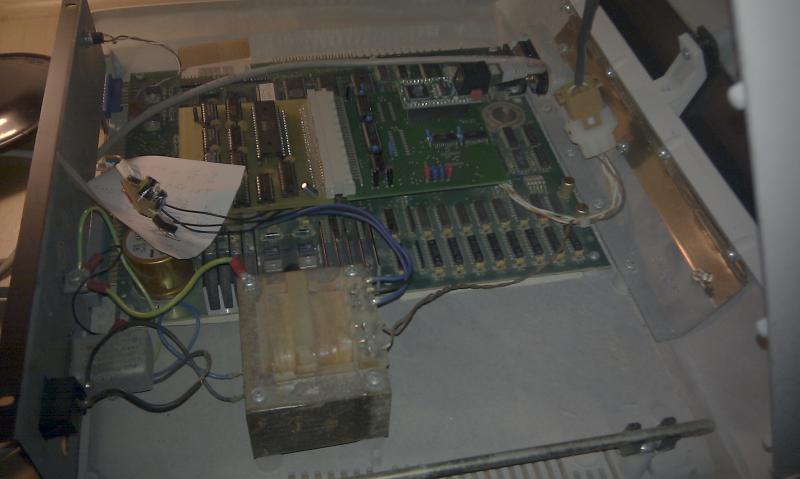
The board is installed "under" the 6502 CPU, i.e. the 6502 is taken of the Commodore's board and put onto the board. Then the board is put in place of the 6502 CPU on the Commodore board.
To use it, you have to write to the control registers at $e808 and $e809 (both are write-only) The control port is $e809 and has 2 bits. If bit 0 is set, the board mapping is enabled. Bit one determines whether the CS/A I/O or memory bus is used. I zero, then CS/A memory (/MEMSEL) is used, if it is one then I/O (/IOSEL) is used.
The board maps 4k byte. So the CS/A I/O are at $e800-$efff is mapped twice, depending on whether the used board decodes A11. If memory is used, then the adapter needs to set the upper address bits A12-A19. This is done by writing these address bits to $e808.
Use in other systems
You should even be able to use the board in other 6502-based systems. The bus decodes addresses in 4k blocks, but of the control block only 16 addresses are used ($80x), and of the map block only those areas are used that are decoded by the CS/A board.
Thus if your system has the relevant address areas unmapped, you should be able to use the board also!
Version: 1.2b
Status: untested
Notes
| This board has not been tested yet. The schematics is basically the same as the 1.1A version. | |
| Compared to the 1.2a version it exchanges the polarity of the power connector, so it is compatible with the other boards I did (e.g. the PET816 accelerator board), namely GND in the middle now and VCC on the outer pins. |
Version: 1.2a
Status: untested
Notes
| This board has not been tested yet. The schematics is basically the same as the 1.1A version. | |
| This board version adds a power plug, 3.3V generation, a second CS/A bus adapter (so you can use it in a 8296 and a 3032), and some more jumper options. Layout such that it should fit into a 8296 and a 3032 (not tested yet though). |
Version: 1.1a
Status: prototype
Notes
| This board has been tested with a 8296 only. A later test with a 3032 (i.e. a board without CRTC) shows that the CS/A board would reach out of the case, thus the adapter does not work there. | |
| It seems that the board requires a separate power supply. When POKEing data into the BIOS memory, it works when between pokes there is enough time (e.g. a PRINT statement), but misses some writes when not. | |
| The layout could be better. In a 8296 it reaches over the main board power connector. I had to use a stack of 40-pin sockets underneath to reach the necessary height. |
Files
| petcsadesc-v1.1.txt | |
| pet_csadapter-v1.1a.sch | |
| pet_csadapter-v1.1a-sch.png | |
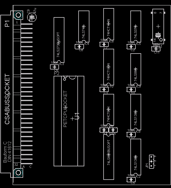
| pet_csadapter-v1.1a.brd | |
| pet_csadapter-v1.1a-brd.png | |
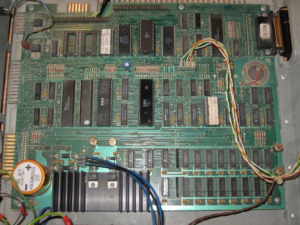
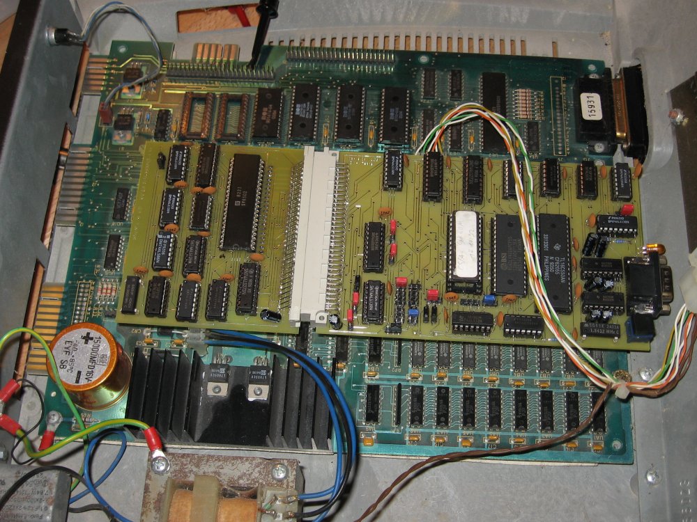
| 8296board.jpg(The original 8296 board) | |
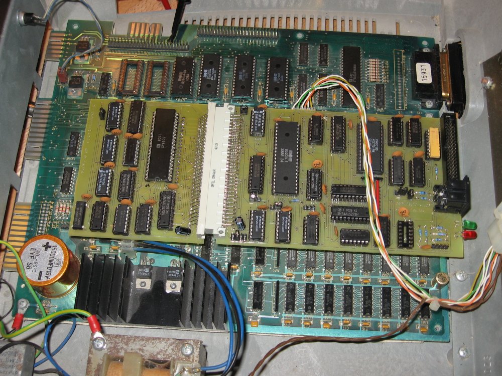
| 8296board+drvio.jpg(The board with adapter and DRVIO board) | |
| 8296board+bios.jpg(The board with adapter and BIOS board) | |
| ../petnet/peteth.jpeg(The board with adapter and Ethernet board (and extra 3.3V generation)) |
Return to Homepage
Discuss my site on this 6502.org forum thread
(Forum registration required to post)
Dive into the retro feeling and build yourself a Micro-PET or a Multi-board Commodore 4032 replica
Need more speed? Speed up your 6502 computer with this 10 MHz 6502 CPU accelerator board
Interested in electronics design? Look at the design lesson I got from Bil Herd, the hardware designer of the C128
Want 64bit? - pimp the 6502 with the 65k processor design!