Commodore Userport USB interface
The userport USB interface provides USB connectivity to the Commodore line of computers - it's designed to work with the PET, VIC20, and C64 (and in extension with the C128).
The USB interface provides the host as well as client USB interface. So you can use USB devices on the PET - see the video below for example - or you can use the PET as device on a PC's USB bus (although not at the same time)!
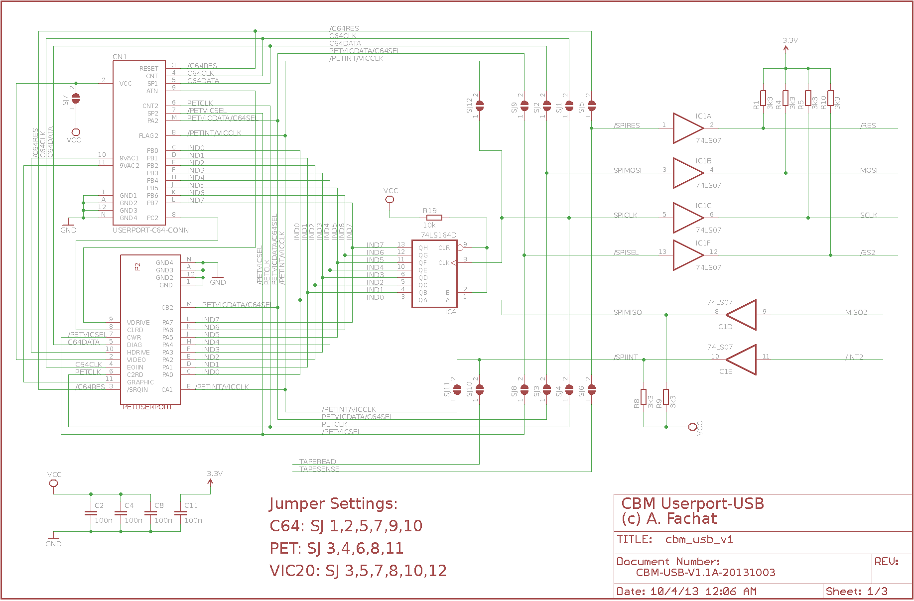
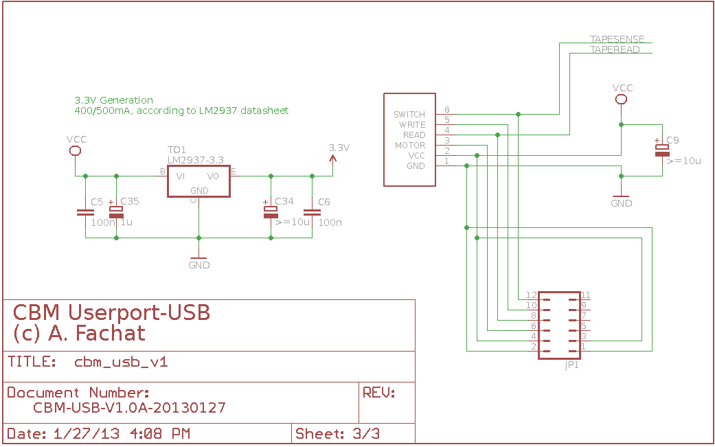
The userport interface actually not only uses the userport, but also the tape port - as there is no supply voltage on the userport (at least on the PET - on the C64 you could conjure up something from the 9VAC). But also the device needs more control lines than available on the userport, so it takes them from the tape port.
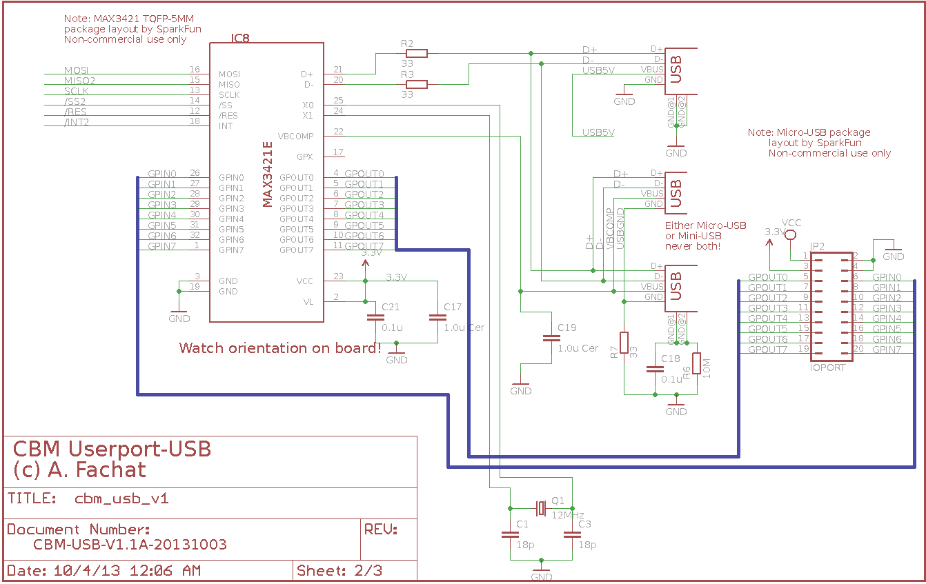
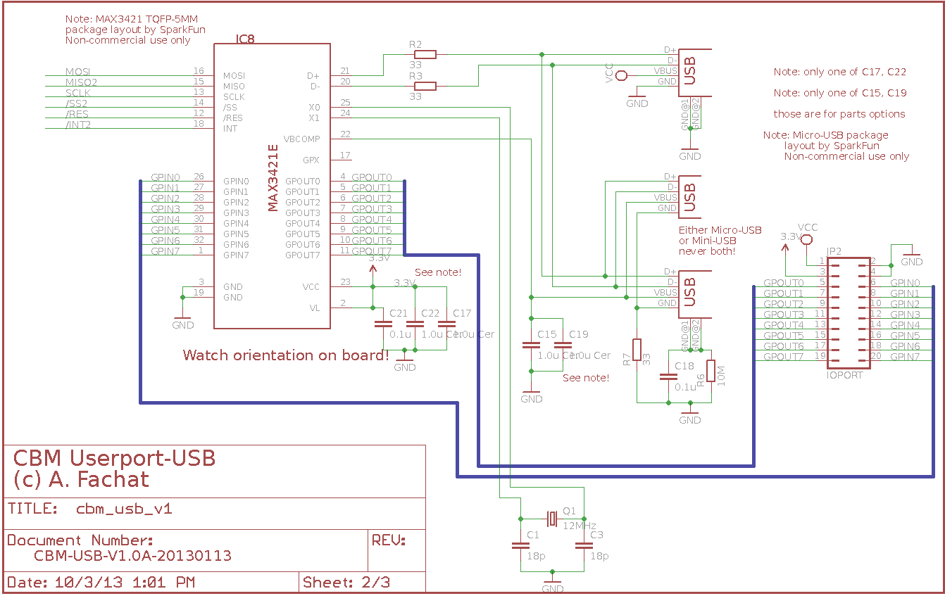
The chip used is a MAX3421 USB interface chip, and the interface board includes some glue logic to connect it to the CBM. The 3421 uses an SPI interface in mode 3 (or, alternatively, 0). Fortunately the VIA uses SPI mode 3 when shifting through its serial shift register. There is only one shift register, though, so shifting out is taken care of by the VIA shift register, the data shifted in (at the same time as data is shifted out) is de-serialized by a simple external 74LS164 shift register and presented as 8 bit parallel data on the userport's I/O port.
- 2013-10-13 Started this page
Table of content
USB65
This driver is a collection of drivers for this and some other platforms. You can find it on github
Please note that since board version 1.1, if you want to use the switchable USB supply voltage, some care has to be taken with the interrupt routine. The PET ROM for example handles the tape MOTOR output - which controls the power supply - in the interrupt routine. If you don't work around this, the power will stay off...
Version: 1.1A
Status: untested
Notes
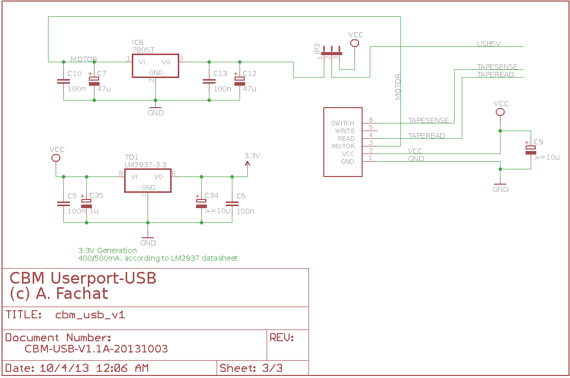
| This version adds a separate - jumperable - way to produce the 5V required by the USB host bus. It uses the tape output of unregulated 9V DC and uses a power requlator separate from the 5V used for the actual USB interface. This way you can switch USB power, and don't have any bad effects of USB power consumption on the actual interface or the main computer itself. | |
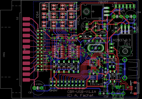
| This version also moves the mini-USB interface to the side, as the assumption goes this will be less used than the USB micro. Some parts options have been removed due to space optimization. | |
| This schematics and board is only derived from some experiments with board version 1.0, and thus untested as a real board. |
Version: 1.0A
Status: ok
Notes
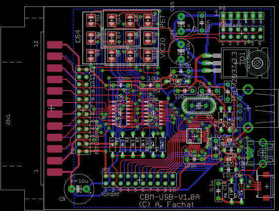
| This is the initial version of the board. And it worked right without further changes! :-) | |
| Although this board has soldering jumpers to work with different types of machines from PET over VIC20 to C64, it has so far only been tested with the PET. |