CS/A65 BIOS
This board implements basic memory and I/O functionality
for the CS/A65 computer.
The BIOS board complements the MMU CPU board in that it provides
some RAM, ROM, and basic I/O (a RS232 interface, that is).
It also has a special I/O port that allows the CPU to read the IRQ line,
or the state of a pushbutton. Also a 50 Hz interrupt is provided that
can be switched on and off with this port, as well as a system LED.
The I/O mapping can be changed from the BIOS port as well.
The older version 1 used a 6551 ACIA for the RS232 interface, but now I
use a 16550 UART (with FIFO).
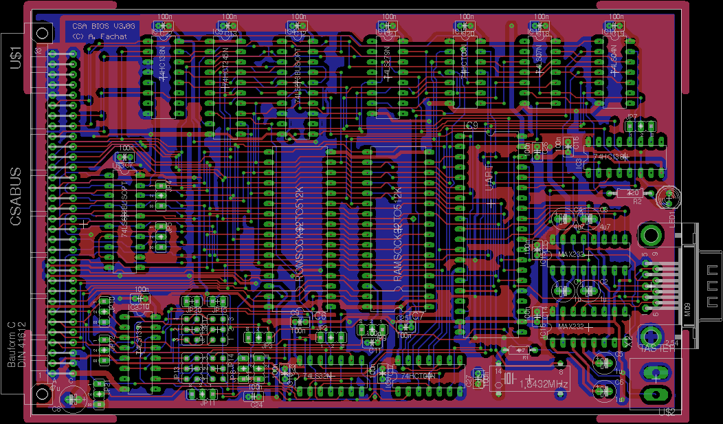
- 2021-10-17 After actually several weeks of debugging and burn-in-testing I found an issue in the /CS line of the SRAM, which is now fixed in version 3.0G
Table of content
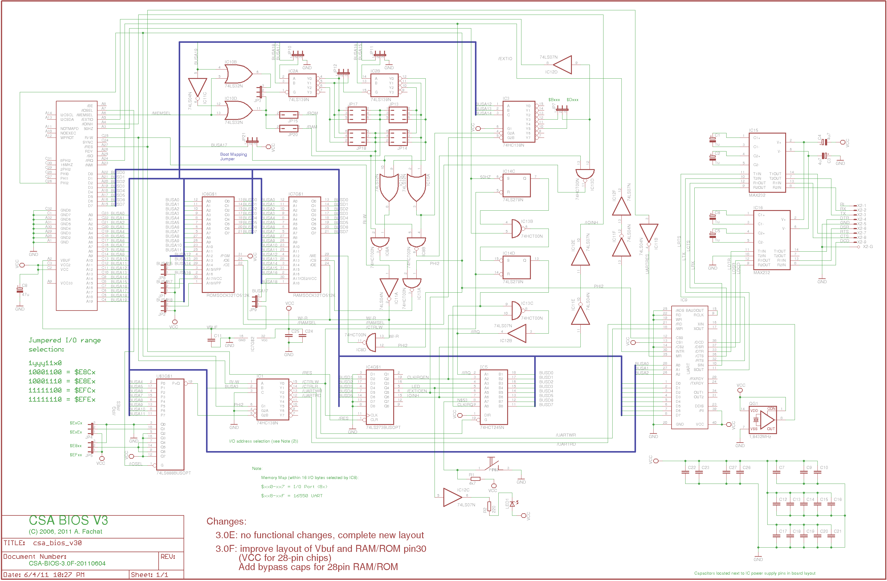
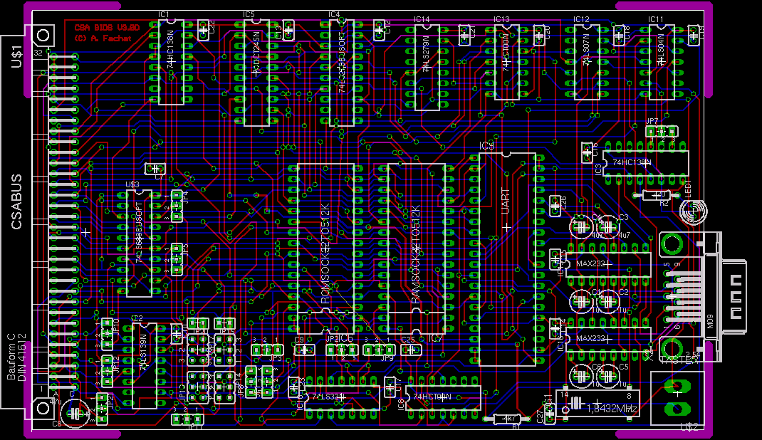
Version: 3.0G
Status: ok
Notes
| I found that an SRAM chip from BSI was creating enough noise on the address lines it seems to become unreliable when its /CS line was gated with Phi2. So here now /OE and /WE are gated with Phi2, but /CS isn't anymore. This fixes the stability problem with this RAM chip. | |
| I have not fully tested this board yet, esp. the power and RS232 problems mentioned below. |
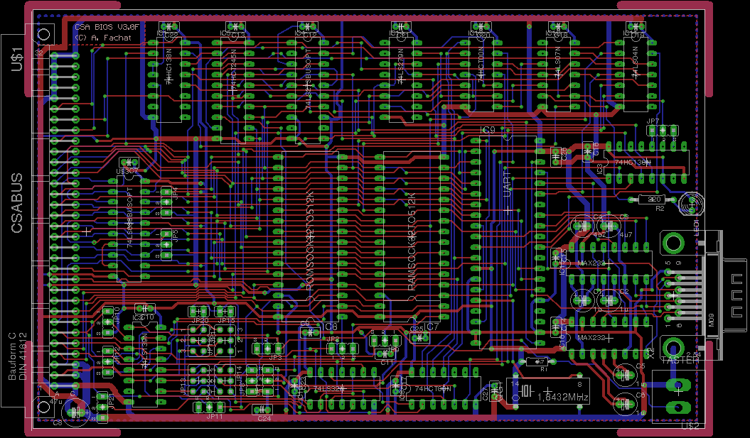
Version: 3.0F
Status: ok
Notes
| This board is a complete re-layout of the 3.0D board. It has no functional changes compared to 3.0D. It has a better layout and two more bypass capacitors to handle 28-pin RAM and ROM ICs. | |
| I have not fully tested this board yet, esp. the power and RS232 problems mentioned below. |
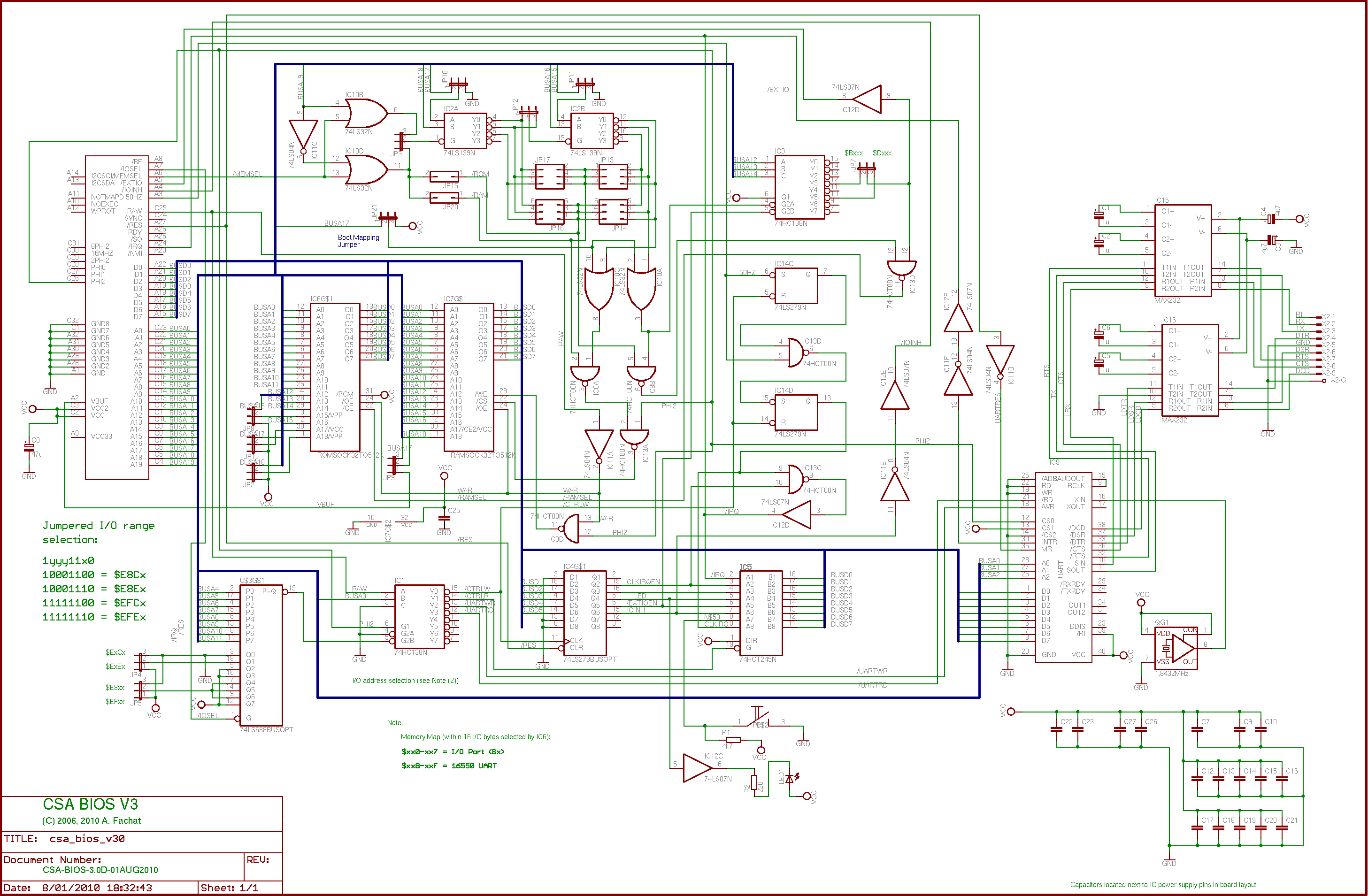
Version: 3.0D
Status: ok
Notes
| This board is definitely in for a re-layout, which will probably happen during the next change (>= 3.1), although nothing's planned yet. | |
| In this version the 512k RAM IC does not get the power supply from the VBuf line (which is 3.6V), but from the real 5V line. I have found that using VBuf made the system unstable as the larger RAM needs much more power. Also my prototype board required a separate MLC bypass capacitor soldered between the Pins 16 and 32 of the RAM IC. | |
| The RS232 problems noted in 3.0B may still be there as I did not change anything. Might be a problem with the power supply though, see RAM chip discussion above. | |
| The TTL parts mainly consist of the 'ALS (advanced Low-Power Shottky) TTL types, except where available. |
Version: 3.0C
Status: ok (for 32k RAM)
Notes
| I have found stability problems with the 512k RAM version. Looking into the datasheet of the used RAM it says that Ax must be stable while /WE is low - so I gated /WE with Phi2. Didn't help though, see version 3.0D. |
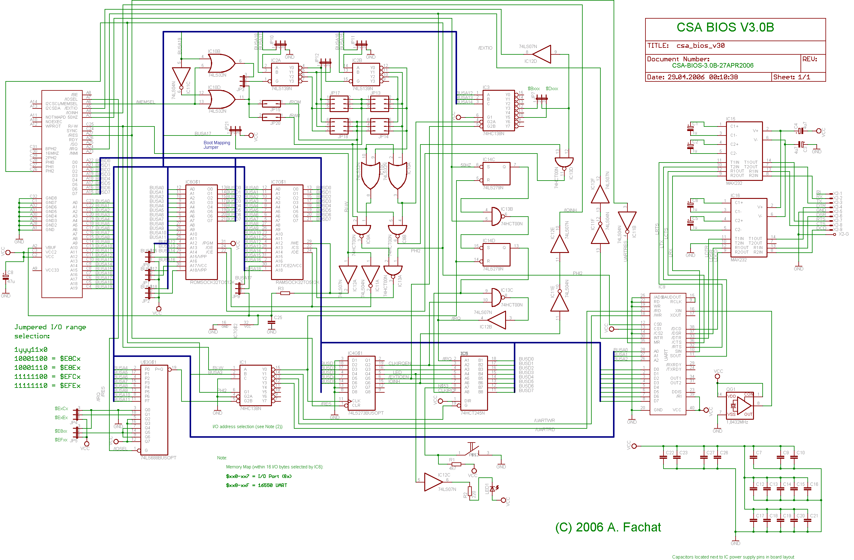
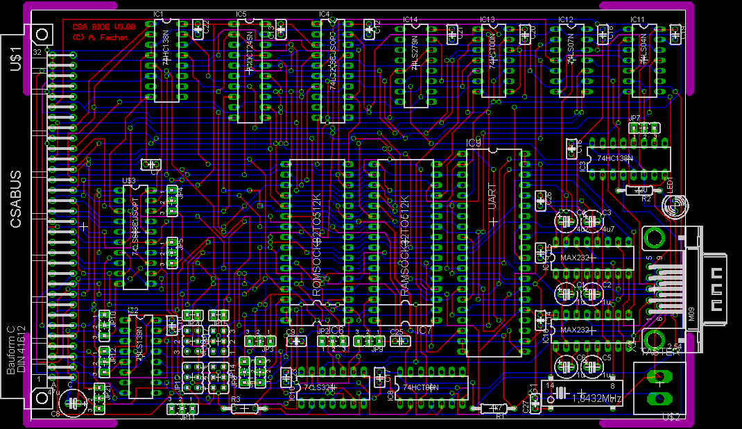
Version: 3.0B
Status: ok (for 32k RAM)
Notes
| This is the new version of the board, using larger (up to 512k) RAM and ROM sockets. For this board also Eagle(tm) schematics and layout files are available | |
| The RS232 functionality works, although it seems larger capacitors for the RS232 voltage generation could be needed, as my test board looses characters. The same schematics works fine in the Gecko board, though. | |
| The TTL parts mainly consist of the 'ALS (advanced Low-Power Shottky) TTL types, except where available. |
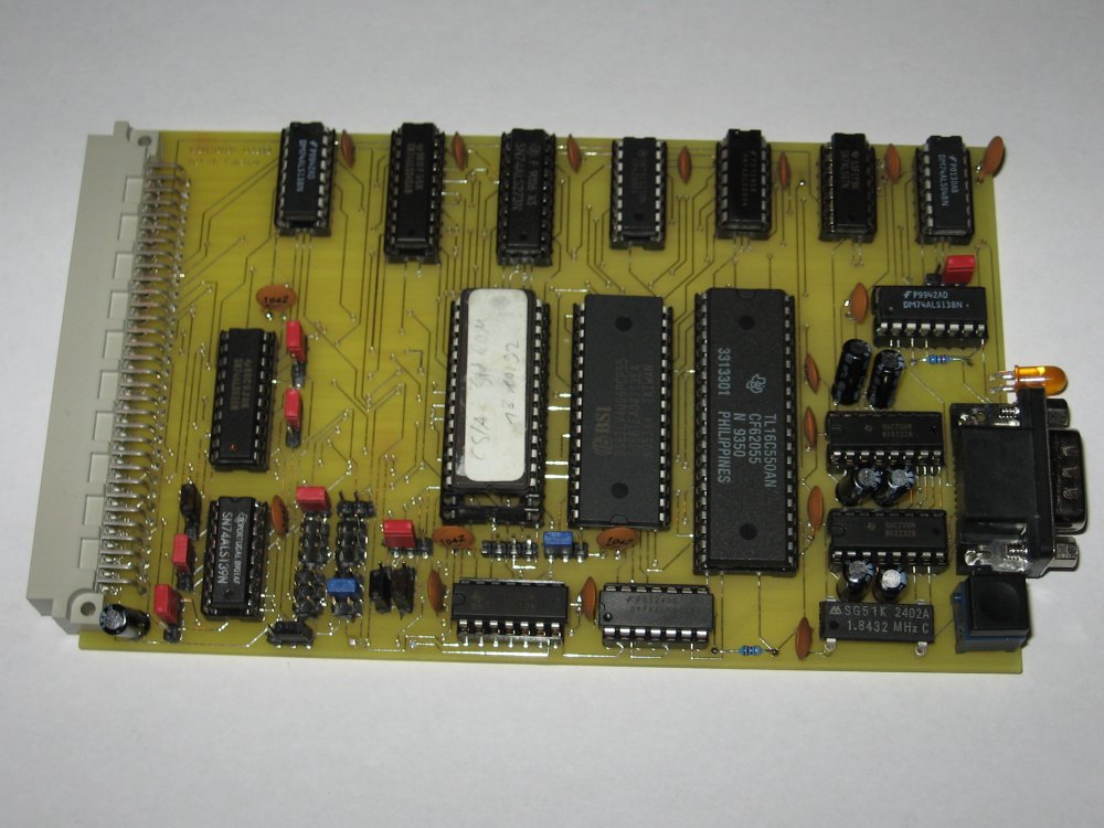
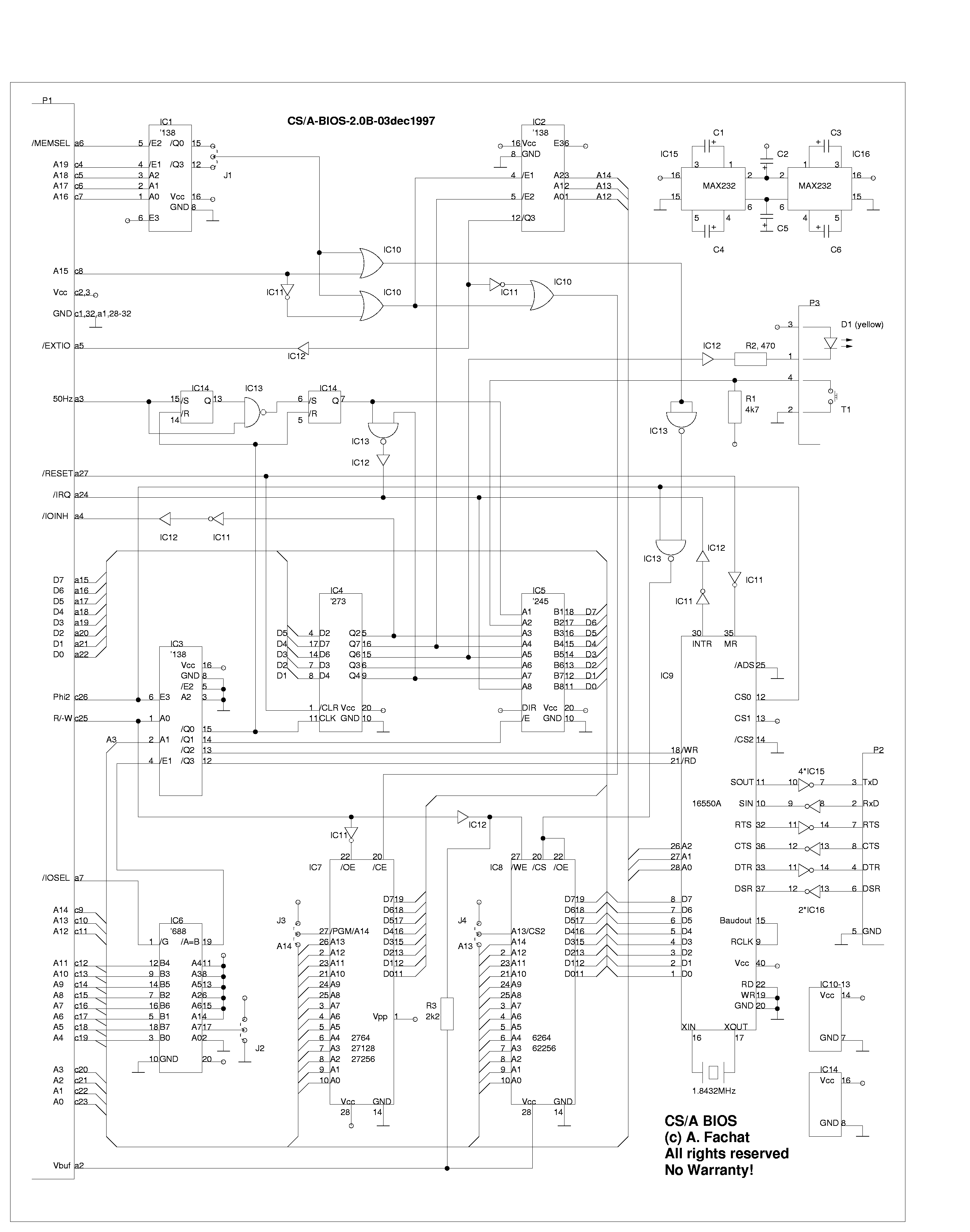
Version: 2.0B
Status: ok
Notes
| This is the old version of the board, using small (up to 32k) RAM and ROM sockets. |
Files
| csabios2.png | |
| csabios2.ps.gz | |
| csabios2desc.txt | |
| csabios2parts.txt | |
| csabios2.jpg(The ROM is currently missing) |
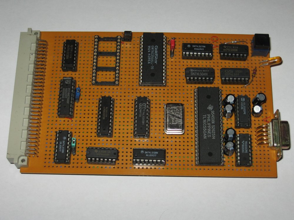
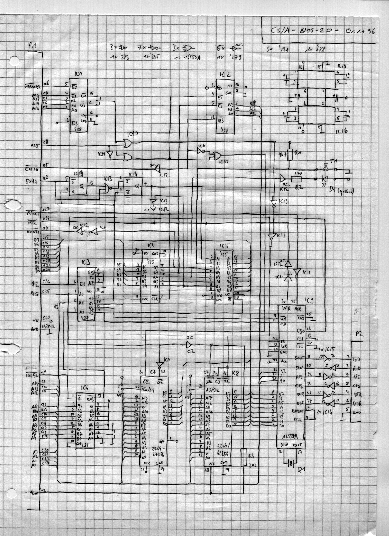
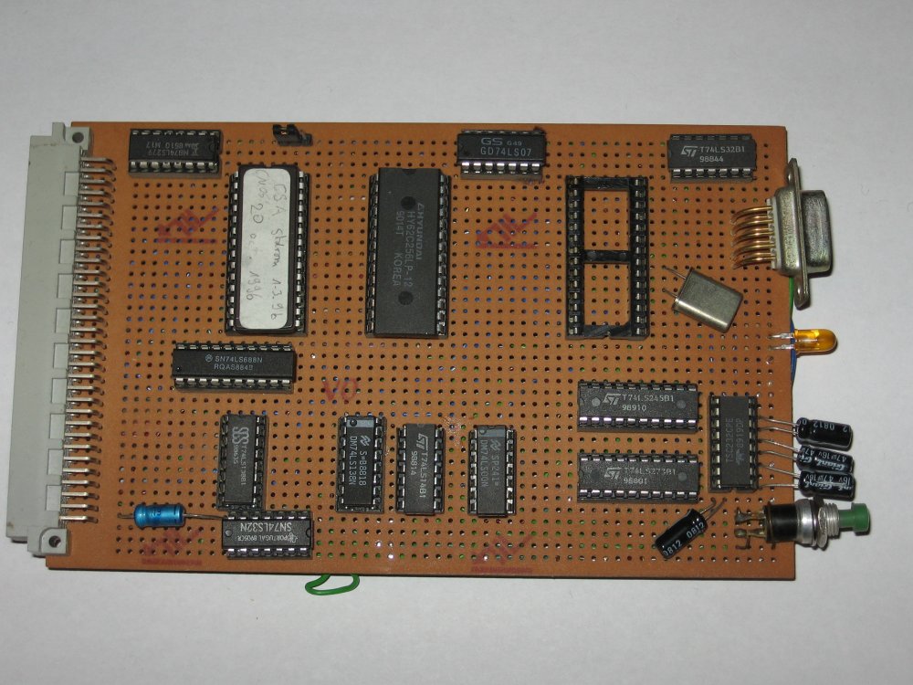
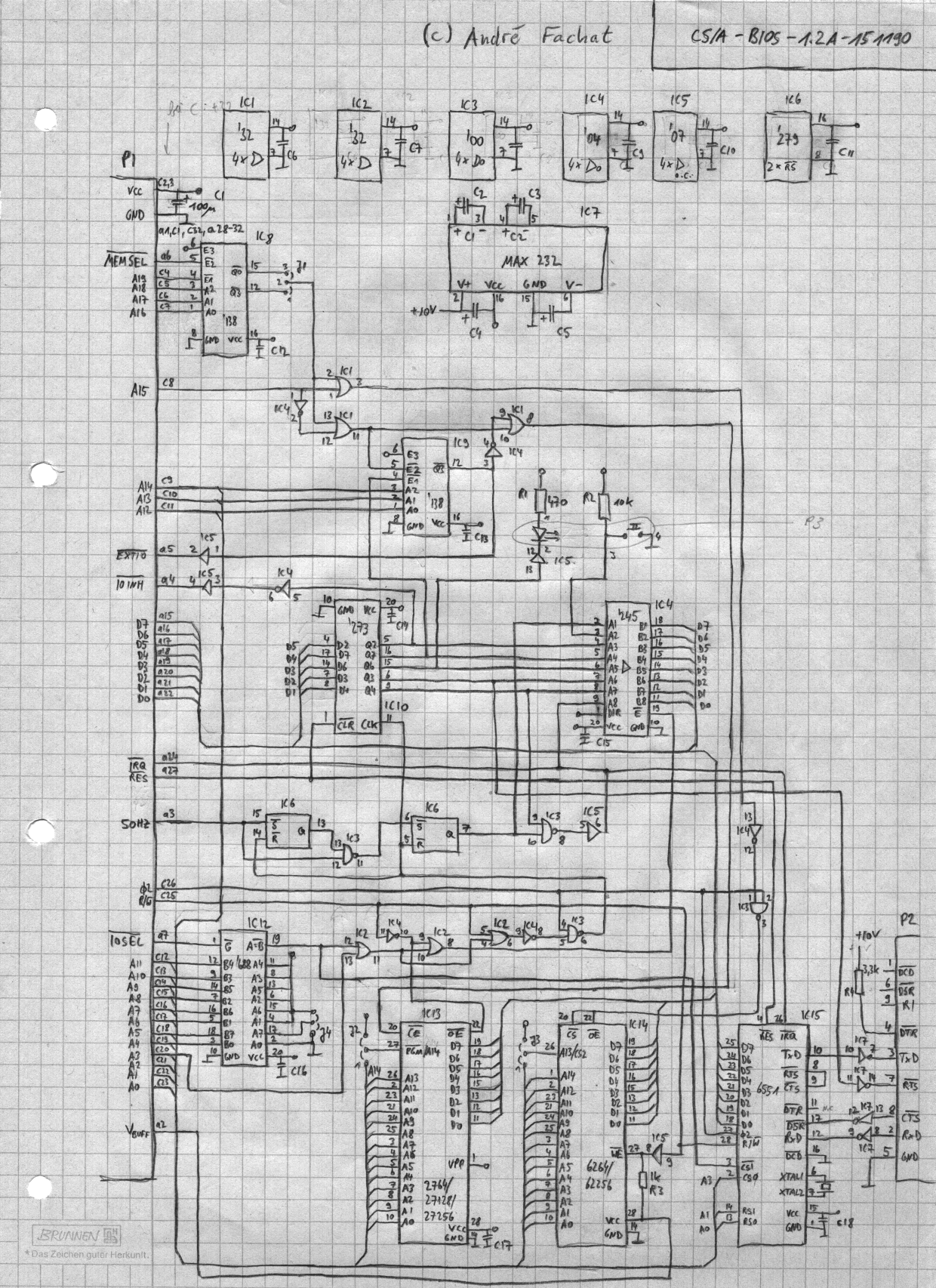
Version: 1.x
Status: deprecated
Notes
| This is the very first version, using an ACIA for the serial interface. It is (here) only documented as a photo and a scanned schematics. |
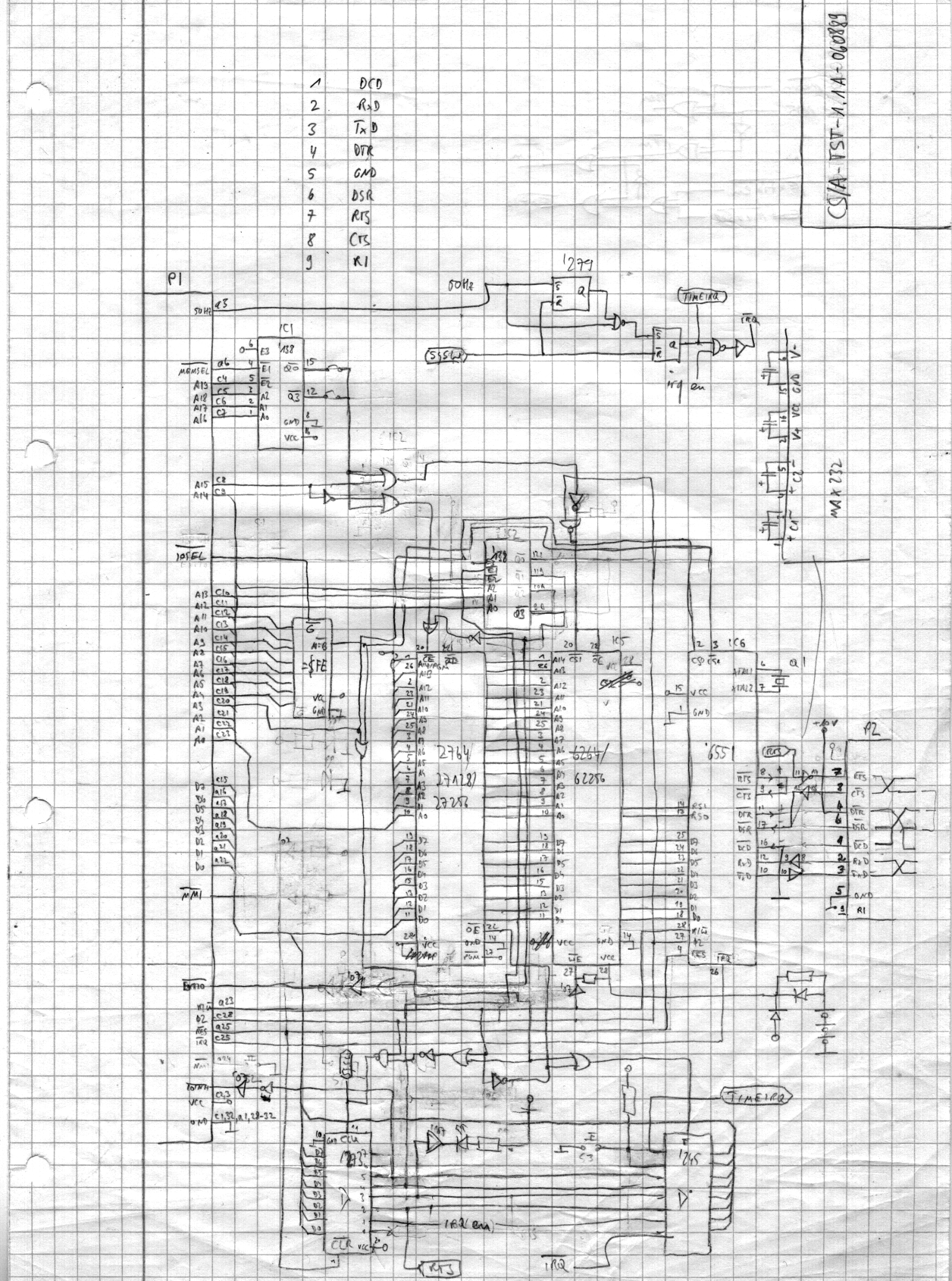
Version: (TST) 1.1A
Status: deprecated
Notes
| This is the very first version, using an ACIA for the serial interface. It is (here) only documented as a photo and a scanned schematics. | |
| This early version was named "TST" instead of "BIOS" :-) |
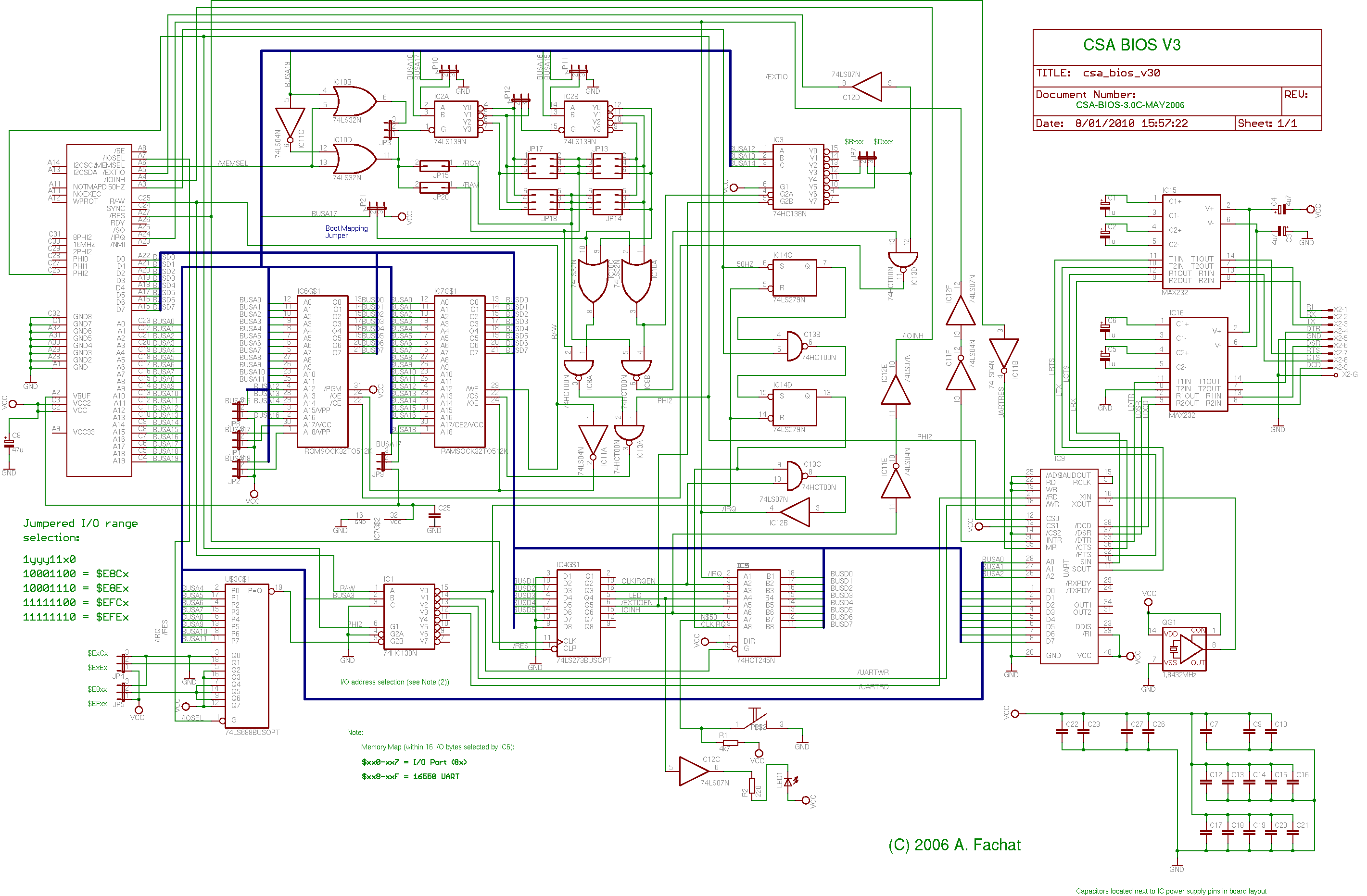
This diagram shows an overview on the board architecture