CS/A65 Power supply
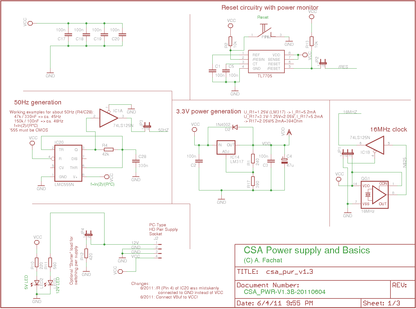
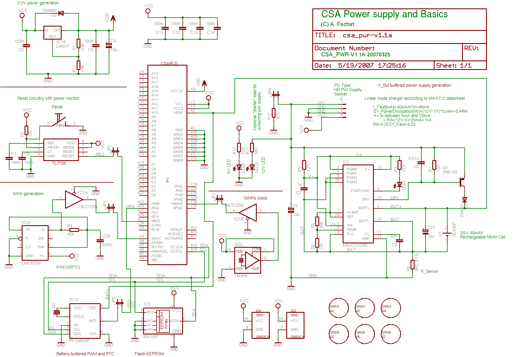
This board implements the basic power supply facilities, using a standard PC power supply as actual supply. It has a 3.3V power generation, a 50Hz signal, as well as battery backup (incl. Li-ion battery charging circuit
Additionally it includes a Reset circuit and a 16MHz clock source, as well as (since 1.1) an I2C realtime clock and flash ROM.
The 3.3V generation uses a standard LM317 voltage generator. The 50Hz generation uses the CMOS (this is important) version of the LMC555. Both schematics come from www.elektronik-compendium.de.
The Li-ion battery charger is a standard schematics from the datasheet of the used MAX712 battery charger.
2010-01-06: Since version 1.2 the board also contains an I2C master
with the related RDY generation as the P8584 I2C master
is not running faster than 1MHz.
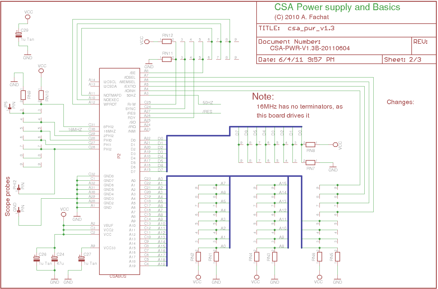
2011-06-04: The new 1.3 version has the I2C stuff removed and instead added the terminator resistor networks so you can use it as a combined terminator/power board, saving one bus slot.
Note, depending on your requirements, any of the 1.1, 1.2 and 1.3 versions can be the right one for you, they are all working.
Note, if your parts tolerances are such that you only below 3.3V, you can replace R17 with a pair of 820 Ohm resistors in parallel. Those together in parallel give 410 Ohm and result in about 3.4V - depending on tolerances.
Table of content
Version: 1.3B
Status: ok
Notes
| This board is another version that completely removes the I2C stuff, but adds the resistor networks for bus termination. So you can save one bus slot by using this board on one end of the bus (and not having to use the separate terminator board). |
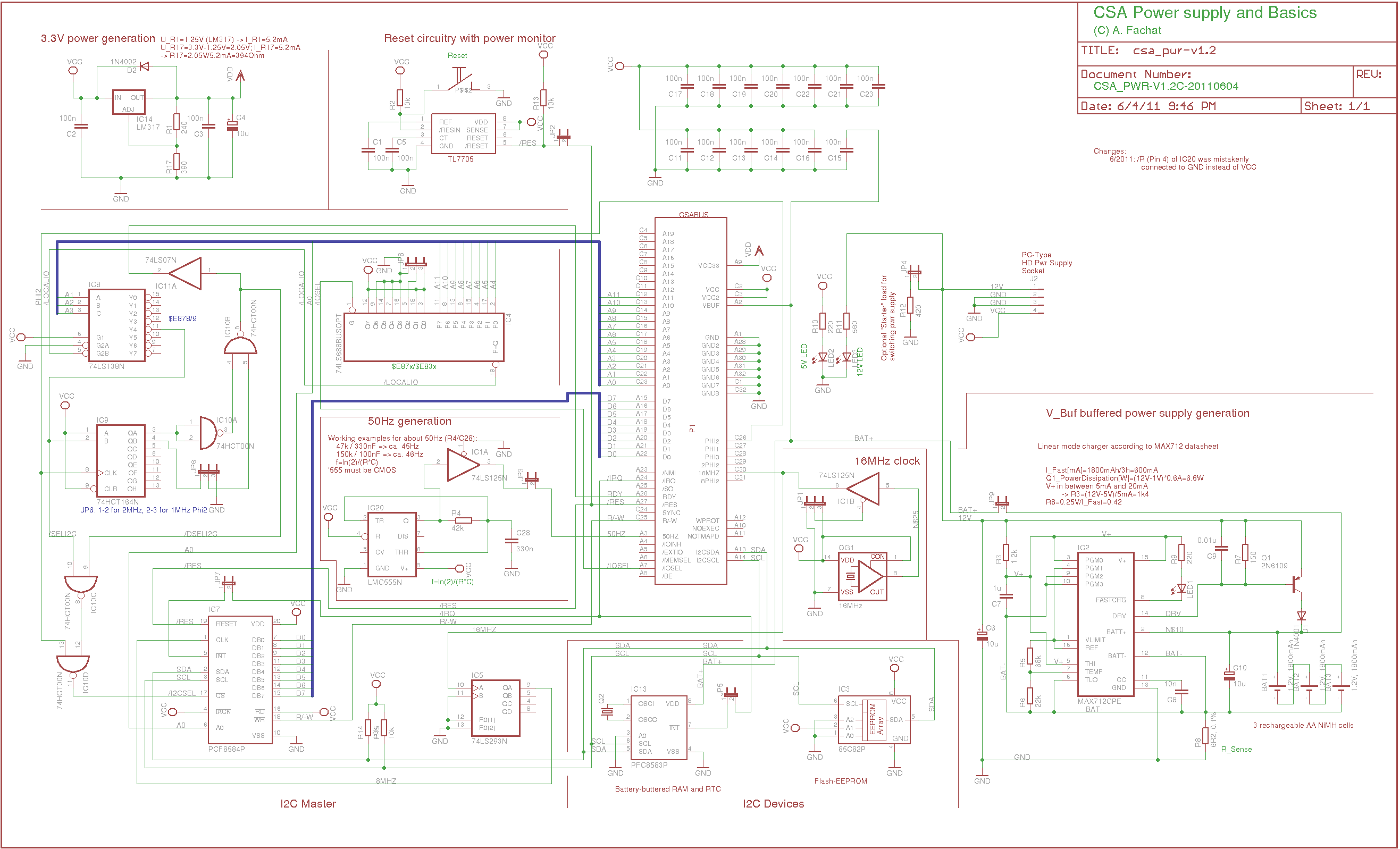
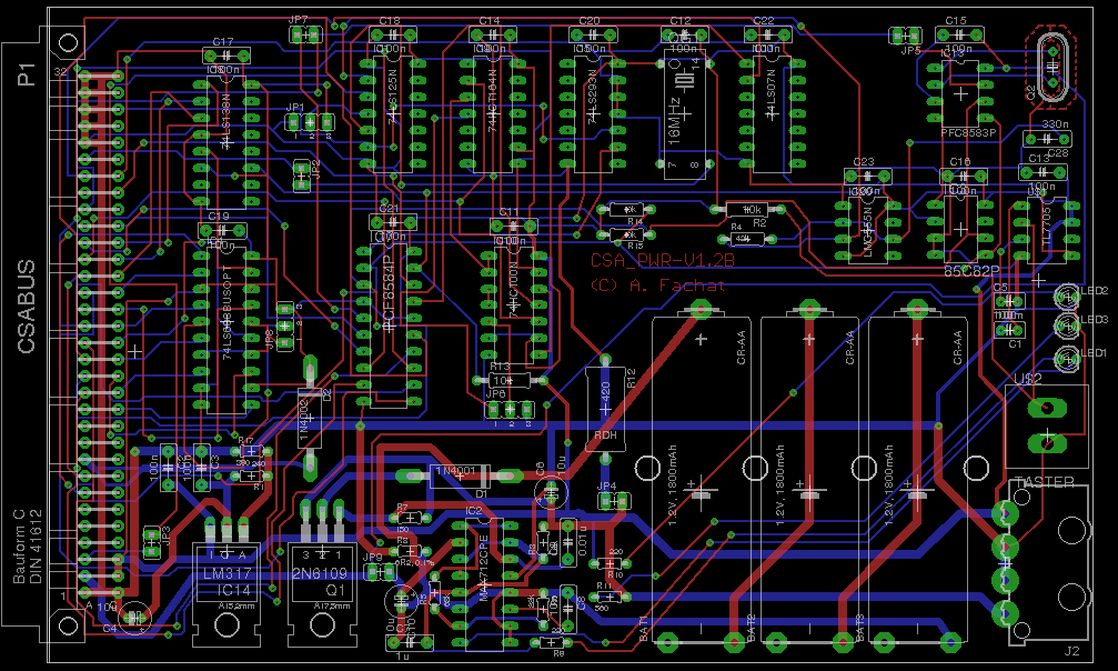
Version: 1.2C
Status: prototype
Notes
| This board fixes the '555 timer bug mentioned on the 1.1B revision. | |
| The layout is untested (I have built it on a 1.2A version) |
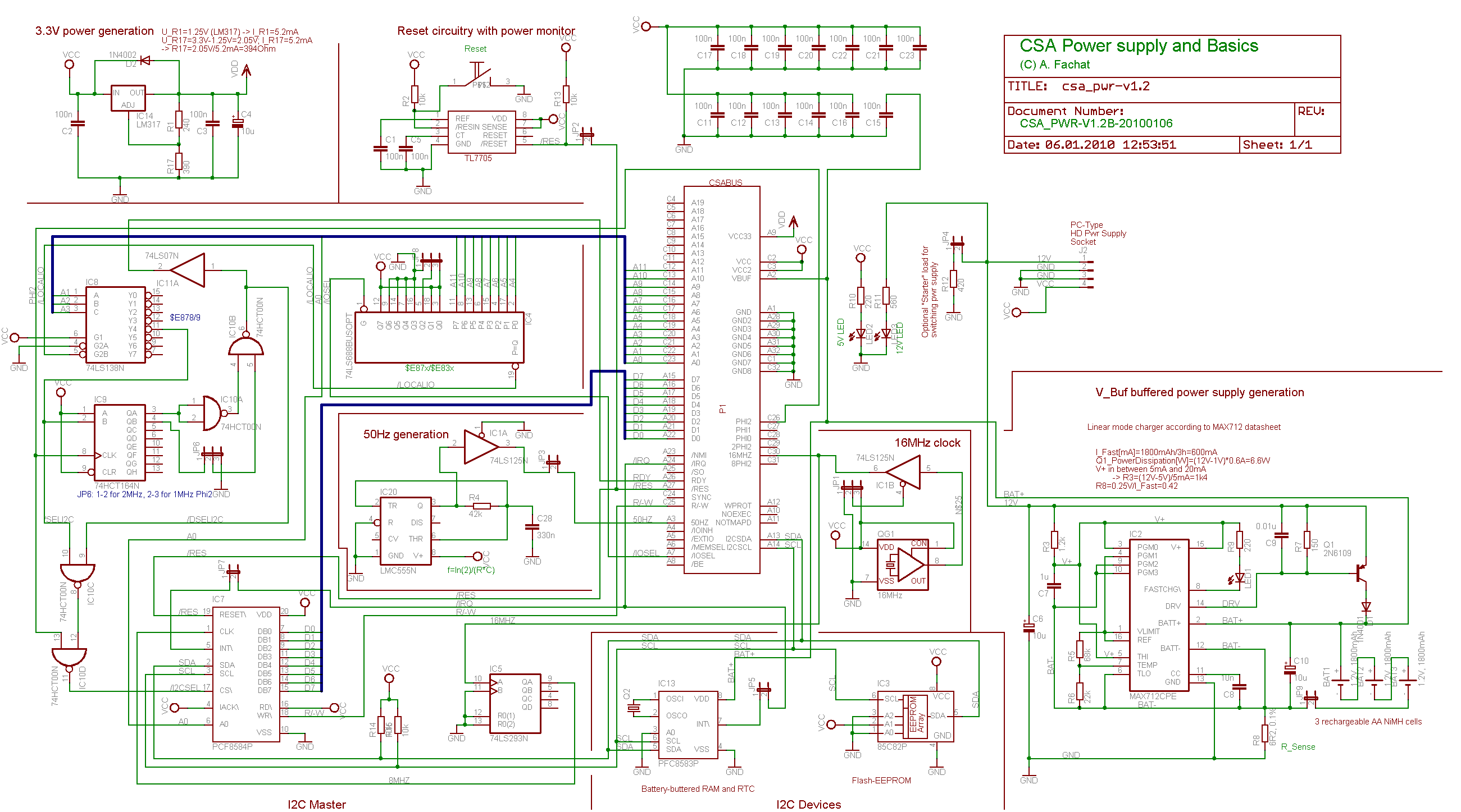
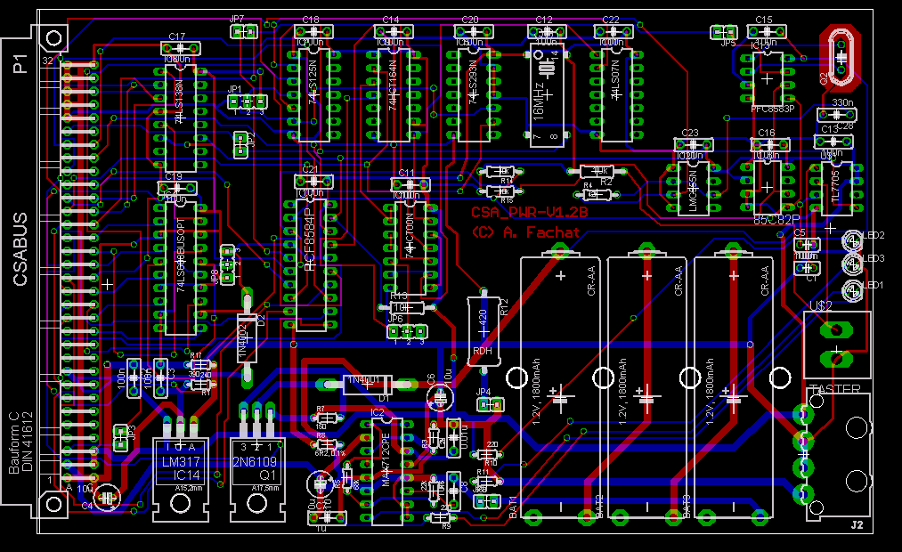
Version: 1.2B
Status: prototype
Notes
This board adds an I2C master (with related Also adds a jumper to decouple the 3.3V from the bus. | |
| The layout is untested (I have built it on a 1.2A version, which is missing JP9 (decouple 3.3V), but also has a serious bug in that it has traces on the top side under the TO220 parts! Therefore I am not publishing the 1.2A version. |
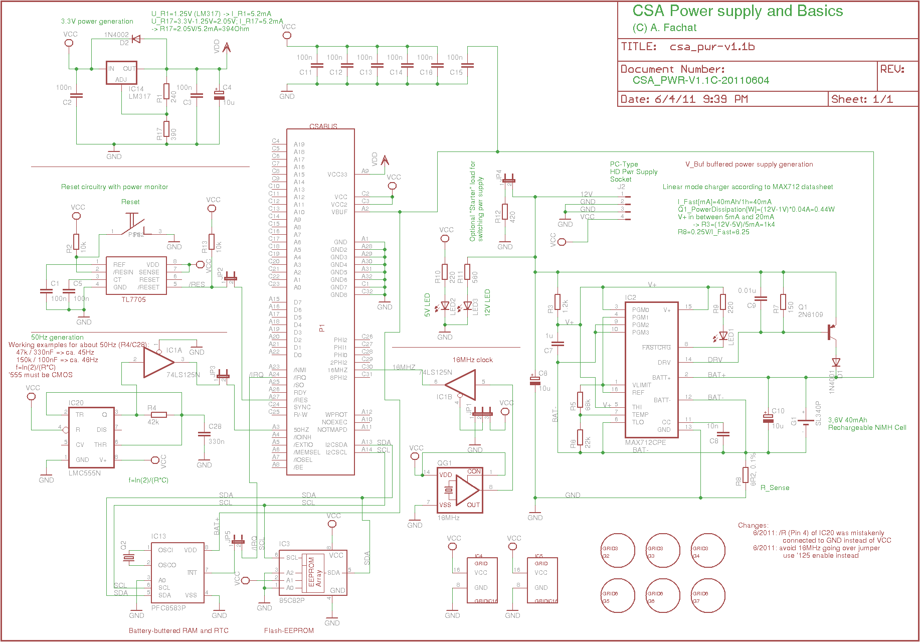
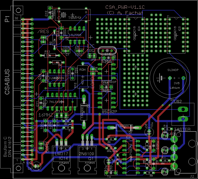
Version: 1.1C
Status: prototype
Notes
| This is a modification of the 1.1B in that the '555 timer bug I fixed on the original prototype is now in the schematics (pin 4 was connected to GND instead of VCC). | |
| The layout is untested. |
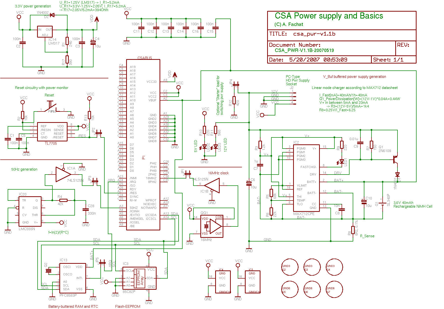
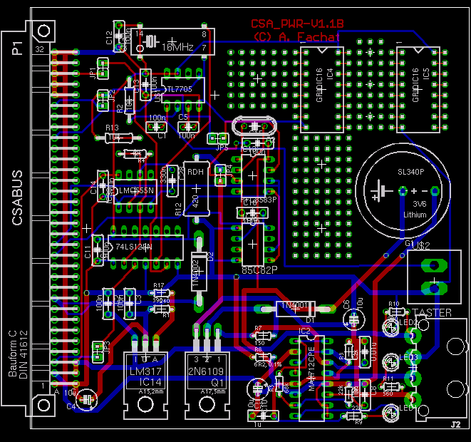
Version: 1.1B
Status: prototype
Notes
| This board has all features. It fixes the bugs in the 1.1A version: no /RESET pullup, wrong R17 value for the 3.3V generation, and decoupling capacitors for the I2C ICs. Also it has the addresses of the I2C chips fixed (in V1.1A they have the same I2C address...) | |
| I found that in the prototype I had fixed a problem with the 50Hz generation - the '555 /RES input was tied low instead of high. This is fixed in 1.1C. | |
| The layout is untested. |
Version: 1.1A
Status: prototype with bugs
Notes
| Watch out, this board has a wrong resistor R17 value and other bugs, see description of 1.1B. |
Files
| csa_pwr-v1.1a.sch | |
| csa_pwr_v1.1a-sch.png | |
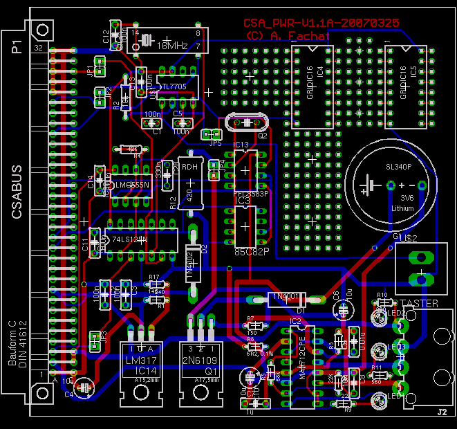
| csa_pwr-v1.1a.brd | |
| csa_pwr_v1.1a-brd.png | |
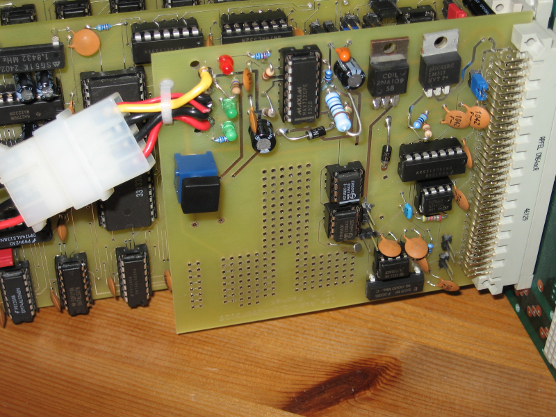
| csa_pwr_v1.1a.png(Without the battery, though) |
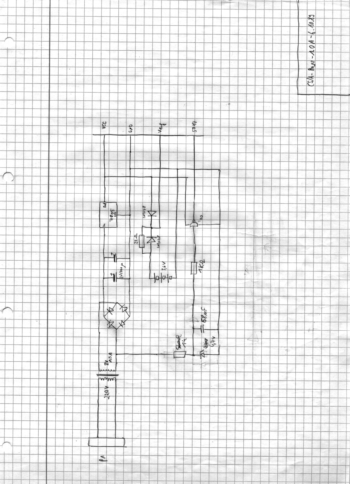
Version: 0.X
Status: broken!
Notes
| This was the original power supply I used. Note it has rechargeable batteries for buffered Vcc in it - but NO appropriate charger! NEVER BUILD THIS! | |
| What might be interesting is the way to generate the 50Hz from the 9VAC |
Files
| csa-pwr-0.X-schem.png |