CS/A65 Auxiliary CPU
This board implements an auxiliary processor for the CS/A65 bus system. The auxiliary CPU watches the bus error conditions signaled via the NOEXEC (no execution allowed, which is checked with the CPU's SYNC line), WPROT (write protection) and NOTMAPD (page not mapped) lines, and in such a case takes over the bus to resolve the problem.
The auxiliary CPU does not have a full MMU, and it does not have own memory either. It uses 32k on the bus for the top and bottom 16k of its address space. Two areas of 4k can be mapped similar to the MMU, and two areas of 4k are set for the bus I/O and the secondary bus I/O.
The auxiliary board has a separate bus socket where another CS/A65 I/O board can be plugged in that the processor can handle independently from the bus I/O.
- 2006-12-27 Published the board.
Table of content
AUXCPU test suite
This test suite contains nine tests that for the auxcpu board:
The tests run in a Caspaer setup, but with Commodore PET ROMs, as described in Roll-Your-Own-Fat40. This way the operating system does not fiddle around with the MMU registers necessary for the test.
- auxcpu1: Tests basic functionality. Loads a program for the auxcpu, and starts it with the "external trigger" functionality. Auxcpu flashes the BIOS board LED and the DRVIO LEDs if the DRVIO board is plugged into the secondary bus of the auxcpu. Does not give control back to the maincpu.
- auxcpu2: Same as auxcpu1, only instead of static RAM from the BIOS board, uses dRAM from the VDC board, to see if the timing is ok there too.
- auxcpu3: blinks the LEDs as well, but after each flash the control is given back to the maincpu that does the actual wait loop until triggering the next flash in the auxcpu.
- auxcpu4: Tests the write protect (WPROT) handling. Maps a page as write protected, and writes to it. The auxcpu prints the fault address on the screen.
- auxcpu4a: Same as auxcpu4, only that the screen memory is mapped using not the MAPRAM, but MAP0 register.
- auxcpu5: Tests the NOEXEC handling. Maps a page as NOEXEC, and jumps to it. The auxcpu prints the fault address on the screen and lets the maincpu return.
- auxcpu6: Tests the "not mapped" handling. Maps a page as not mapped, and reads it. The auxcpu prints the fault address on the screen.
- auxcpu7: Combines NOEXEC, WPROT, and NOTMAPD handling Maps a page as not mapped, no execute, and write protected, and accesses it. The auxcpu prints the fault address on the screen.
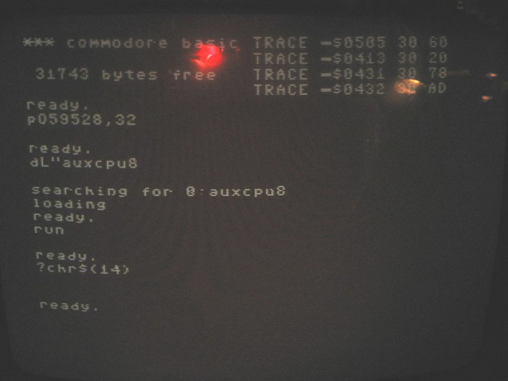
- auxcpu8: Tests the trace feature. Enables trace and prints the next five opcode addresses and opcodes on the screen.
- auxcpu9: Same as auxcpu7, only that the auxcpu also triggers an intterupt for the maincpu.
| auxcpu.tar.gz | |
| trace.jpg(Sample trace output (The first poke is specific for my setup - I'm still using an old charrom - you can ignore it)) | |
| memsetup.gif(This shows the memory mapping used in the test cases.) |
Version: 1.0C
Status: ok
Notes
| In this board the schematics has been tested, the layout has not been tested, though. | |
| This board has been tested in a test setup. The driver above contains the test programs. | |
| The board itself consists of two boards, where the smaller one is piggy-backed on top of the main Euro-card-sized board. The smaller one is called the "addon" board. | |
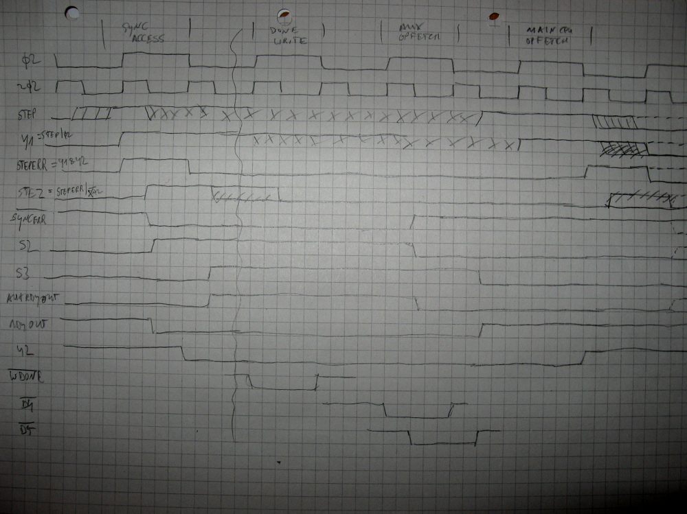
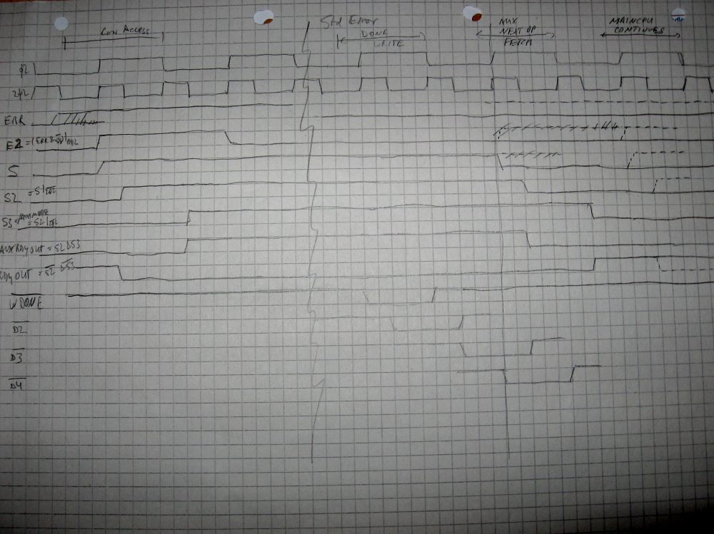
| The two timing diagrams show the timing of various signals on the schematics during the operation. They should help in understanding the boards. | |
| Please note that it still uses the v1.0b version of the addon board. |
Files
| csaauxcpudesc-v1.0c.txt | |
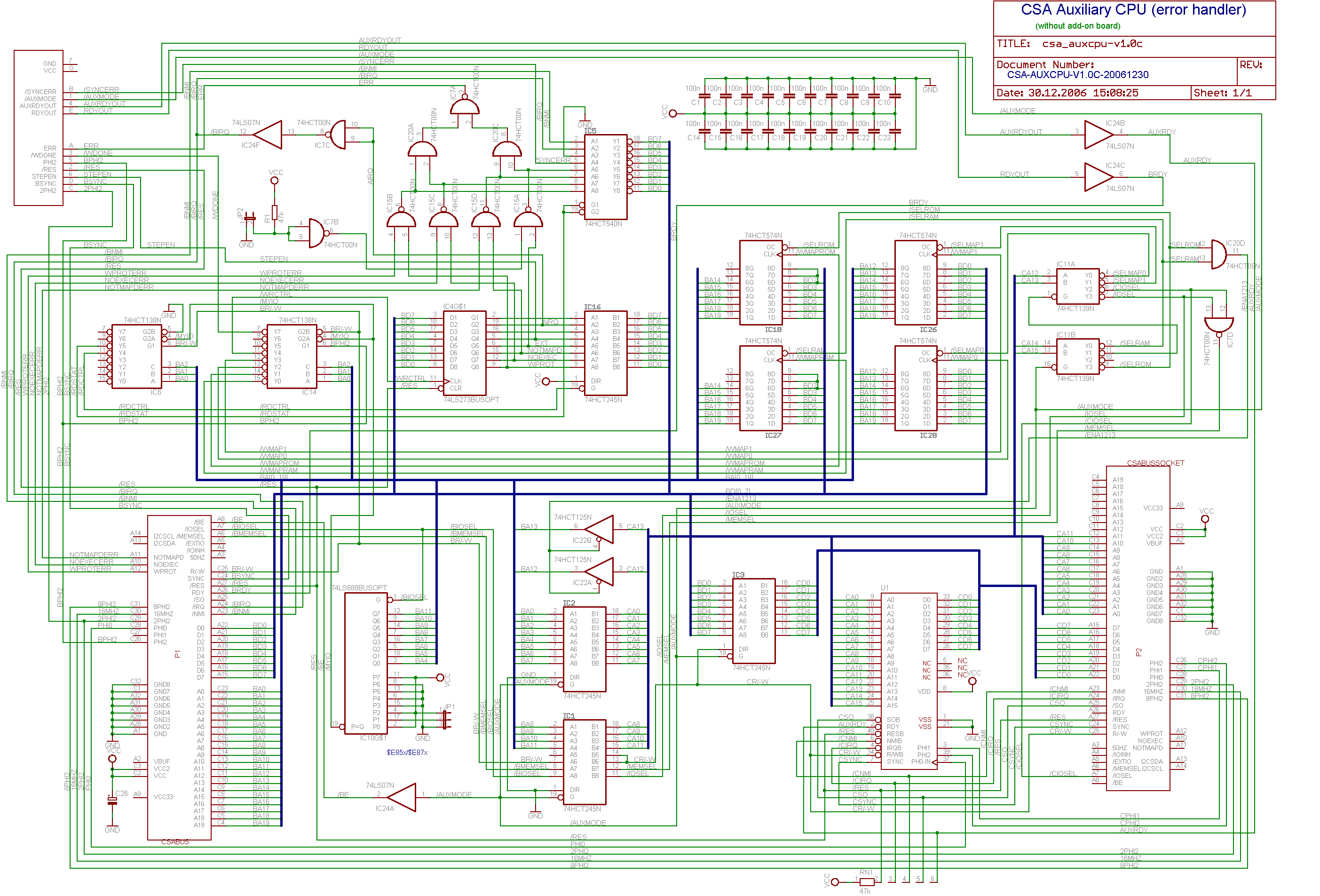
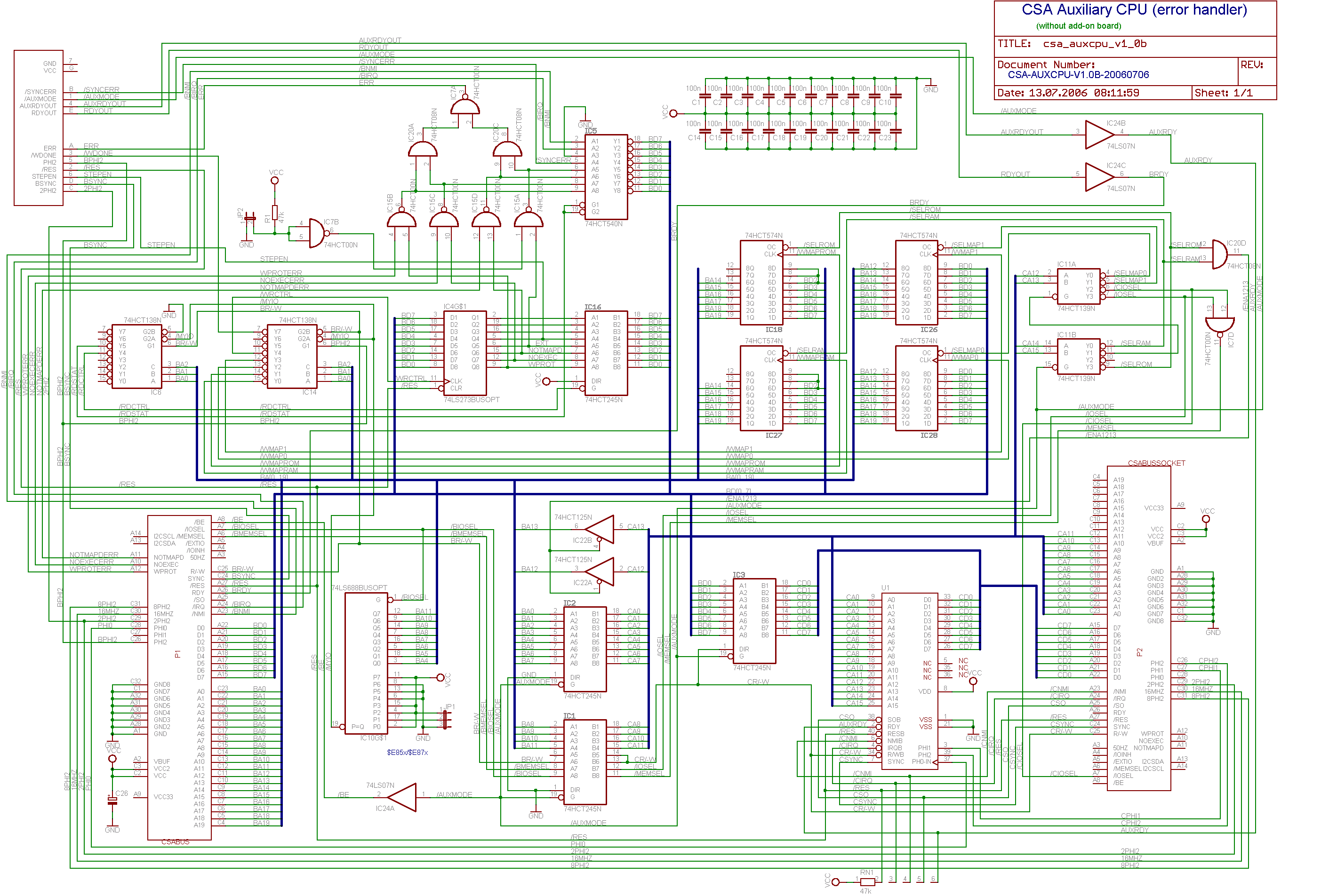
| csa_auxcpu-v1.0c-sch.png | |
| csa_auxcpu-v1.0c.sch | |
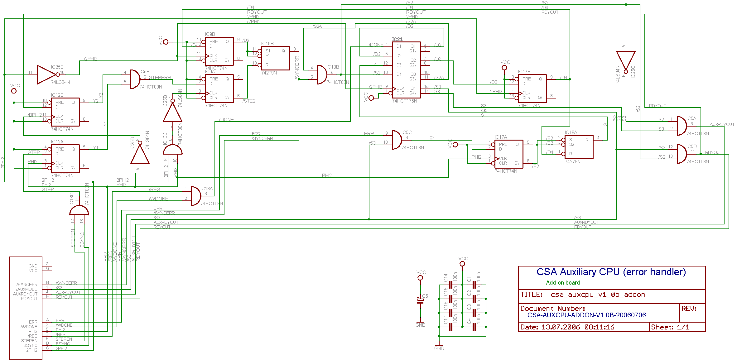
| csa_auxcpu_addon-v1.0b-sch.png(The addon board) | |
| csa_auxcpu_addon-v1.0b.sch(The addon board) | |
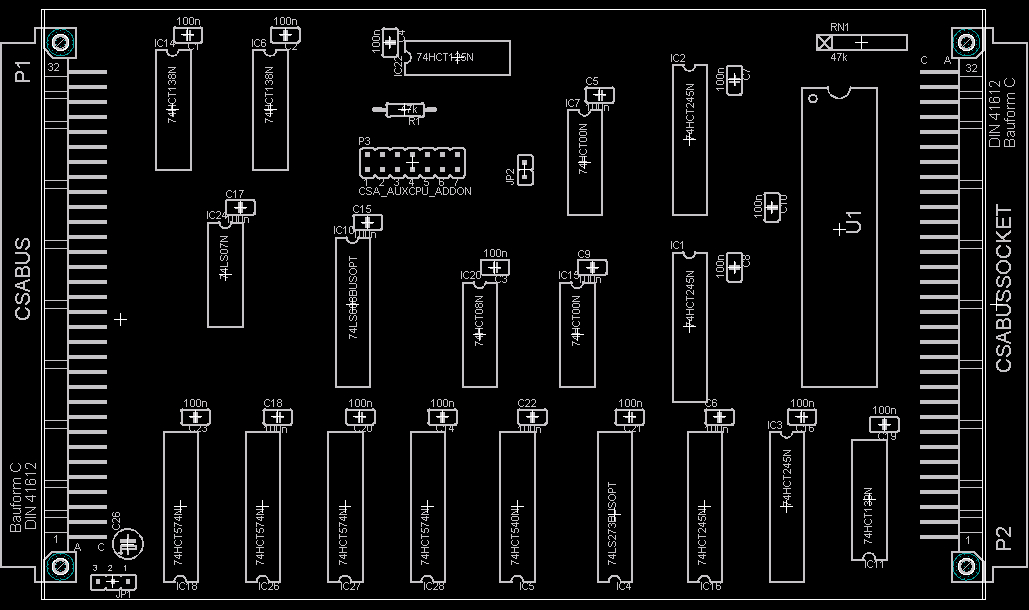
| csa_auxcpu-v1.0c-brd.png | |
| csa_auxcpu-v1.0c.brd | |
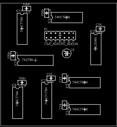
| csa_auxcpu_addon-v1.0b-brd.png(The addon board) | |
| csa_auxcpu_addon-v1.0b.brd(The addon board) | |
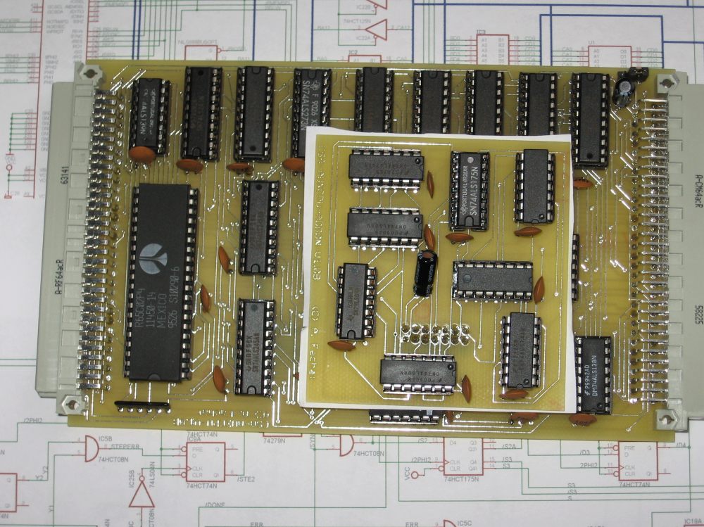
| auxcpubrds.jpg(The complete auxcpu board.) | |
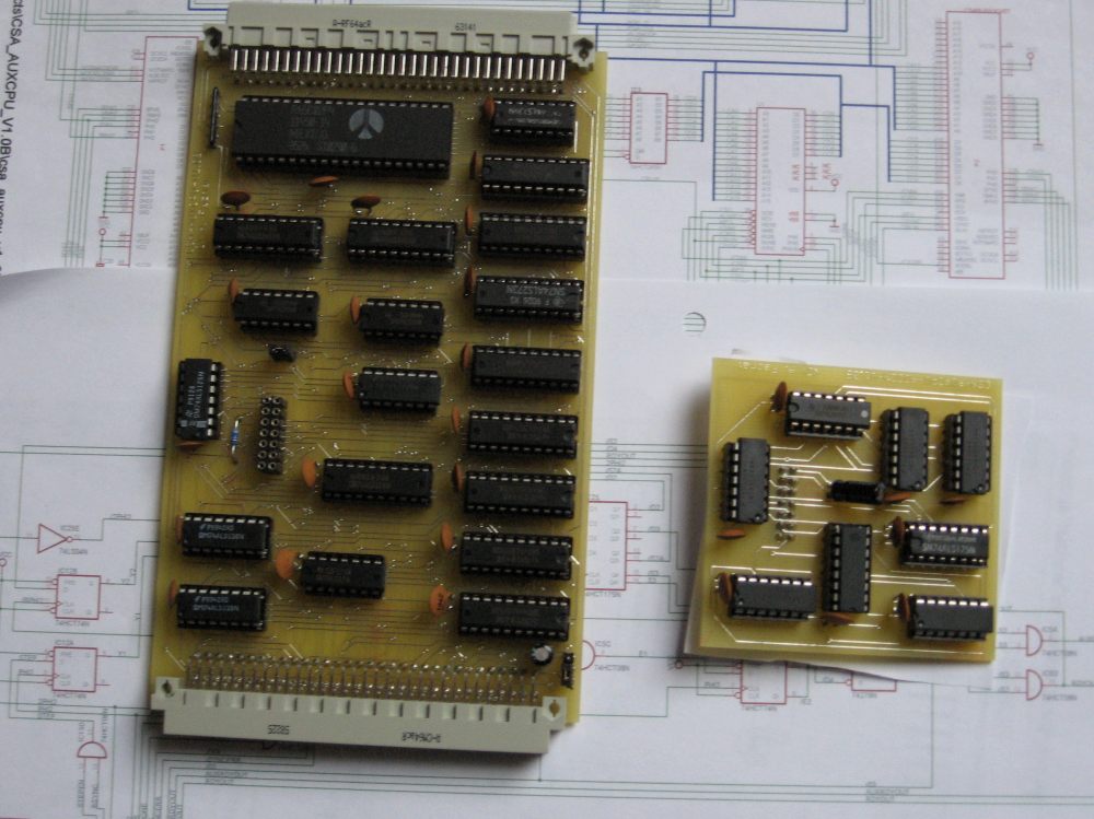
| auxcpubrds-separate.jpg(The two auxcpucessor boards.) | |
| timing1.jpg(Timing sheet 1) | |
| timing2.jpg(Timing sheet 2) |
Version: 1.0B
Status: prototype with bugs
Notes
The following bugs have been found:
| |
| This board has been tested in a test setup. The driver above contains the test programs. | |
| The board itself consists of two boards, where the smaller one is piggy-backed on top of the main Euro-card-sized board. The smaller one is called the "addon" board. |
Files
| csa_auxcpu-v1.0b-sch.png | |
| csa_auxcpu-v1.0b.sch | |
| csa_auxcpu_addon-v1.0b-sch.png(The addon board) | |
| csa_auxcpu_addon-v1.0b.sch(The addon board) | |
| csa_auxcpu-v1.0b-brd.png | |
| csa_auxcpu-v1.0b.brd | |
| csa_auxcpu_addon-v1.0b-brd.png(The addon board) | |
| csa_auxcpu_addon-v1.0b.brd(The addon board) | |
| auxcpubrds.jpg(The complete auxcpu board.) | |
| auxcpubrds-separate.jpg(The two auxcpucessor boards.) |