André 's CS/A65 computer
(C) 1989-2019 André Fachat
On this page are a few images of my selfbuilt computer, to give some impression of how it looks like and of what kind of technique it is. (Remember, I built this thingy aroung 1989-1991, quite some time ago...)
So, celebrate the 30th anniversary of this machine with some new images, and of course with an improved web design for the page!
- 2019-08-31 Overhauled the page and added more pictures to celebrate the 30th anniversary of the CS/A65 computer!
Table of content
This section shows what I currently have, in a way, as the pinnacle of the current design....
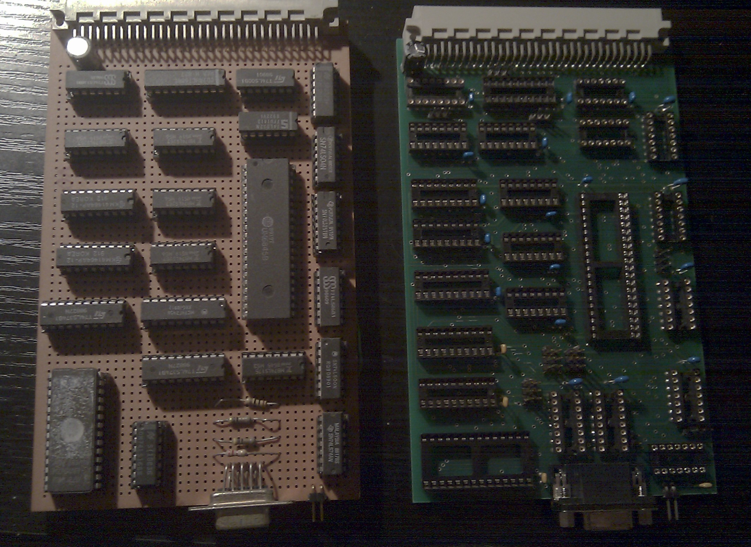
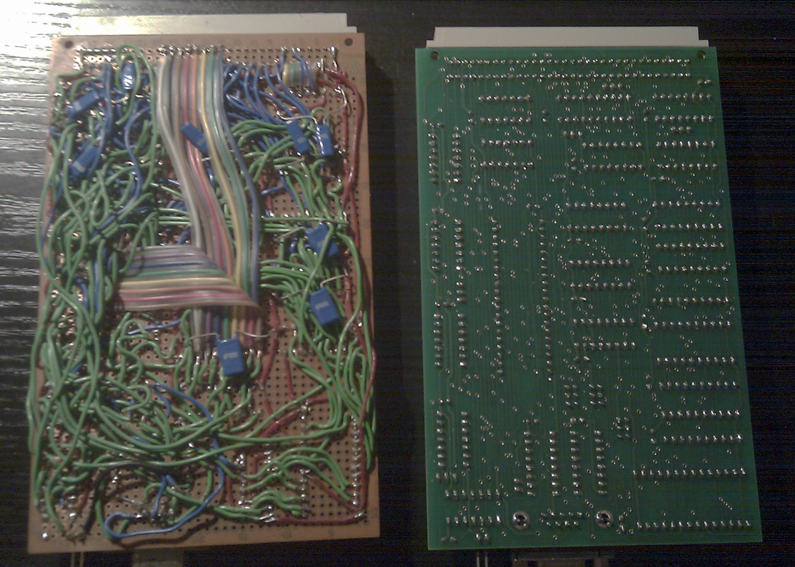
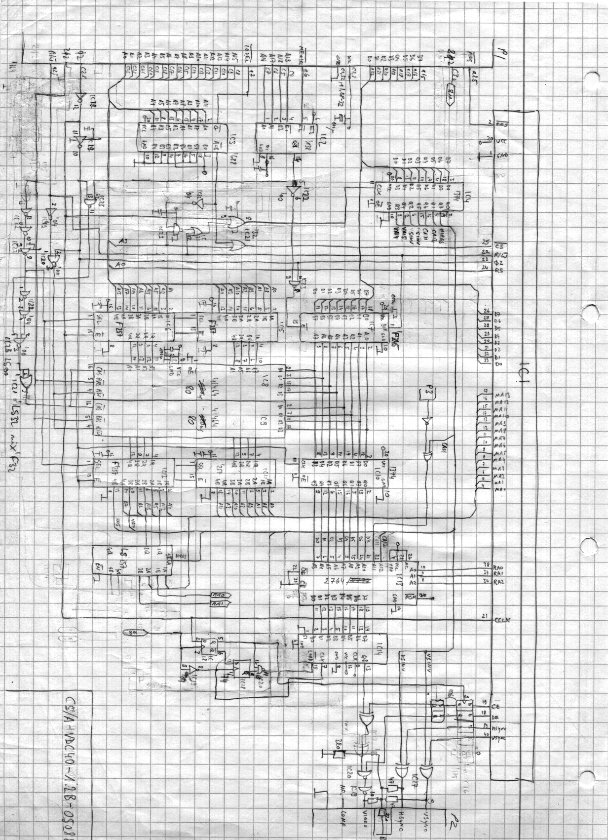
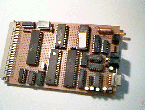
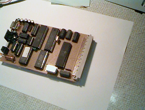
In the beginning, I made my schematics by hand, and soldered everything on perfboard manually. I actually bought an etching kit for PCBs, and got one CPU board etched by someone, but that in the end was not successful, so I stayed with manual soldering.
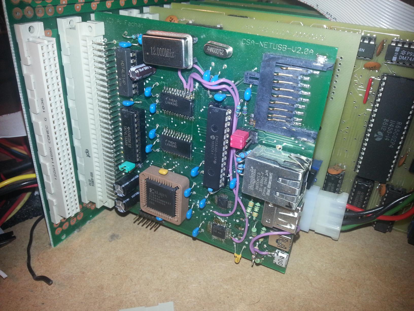
Then, after university, when I had a bit more money to spend, I invested into an Eagle license and moved over from manual soldering to etched boards manufactured by a service on the internet. There was a learning curve, of course.
In the end I was even capable of soldering SMD parts on to such etched boards.
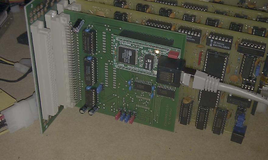
Here you see some examples from the transition
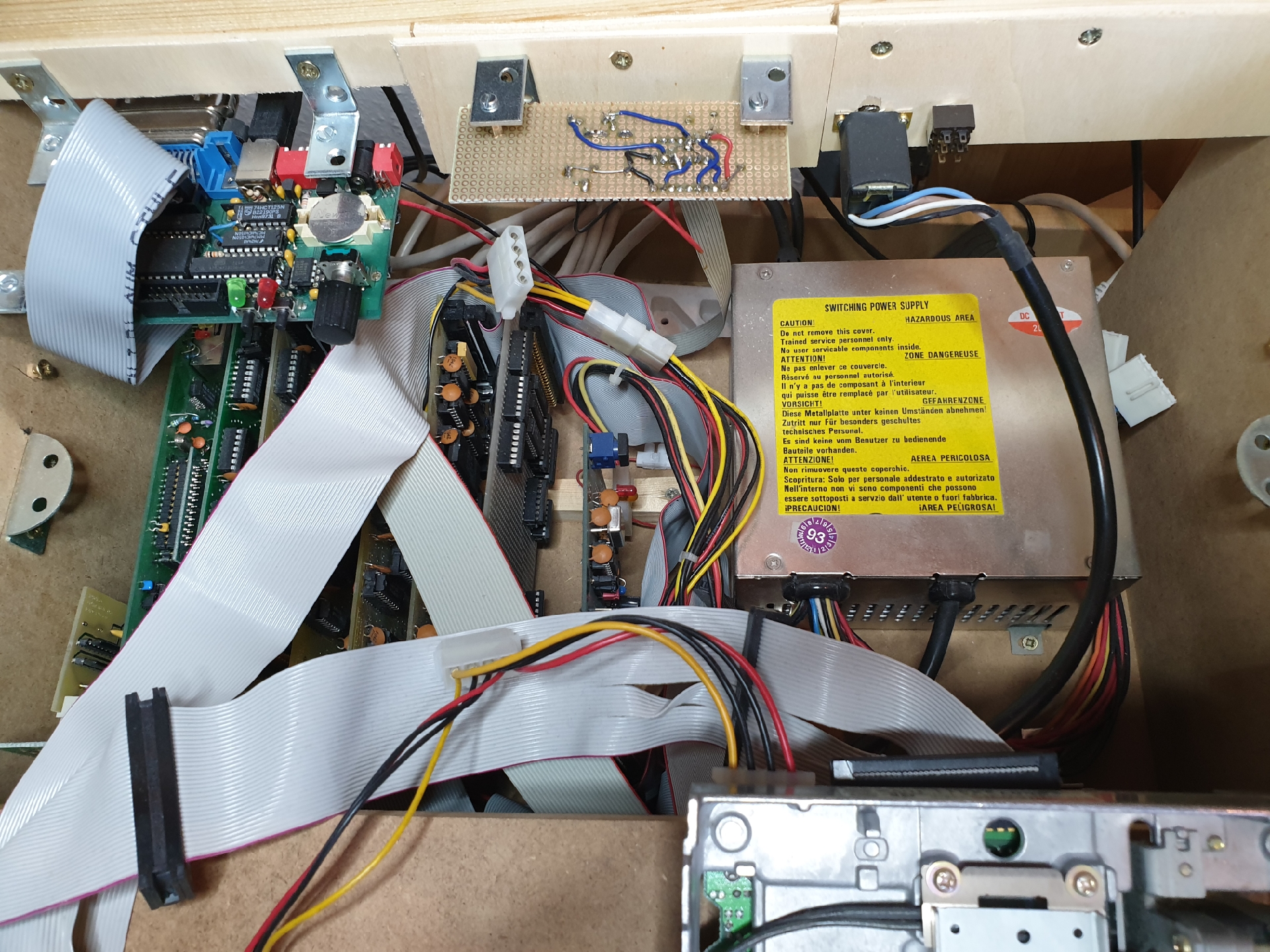
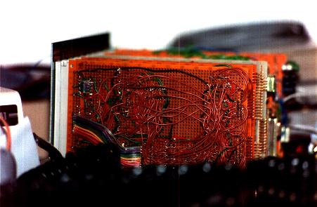
Below is a view of the computer itself. It consists of a passive backplane, and several card boards. From right to left you can see the CPU board, the BIOS board, the video board and the keyboard board. Then there are the IEC board and the shugart bus board to connect PC floppy disk drives.
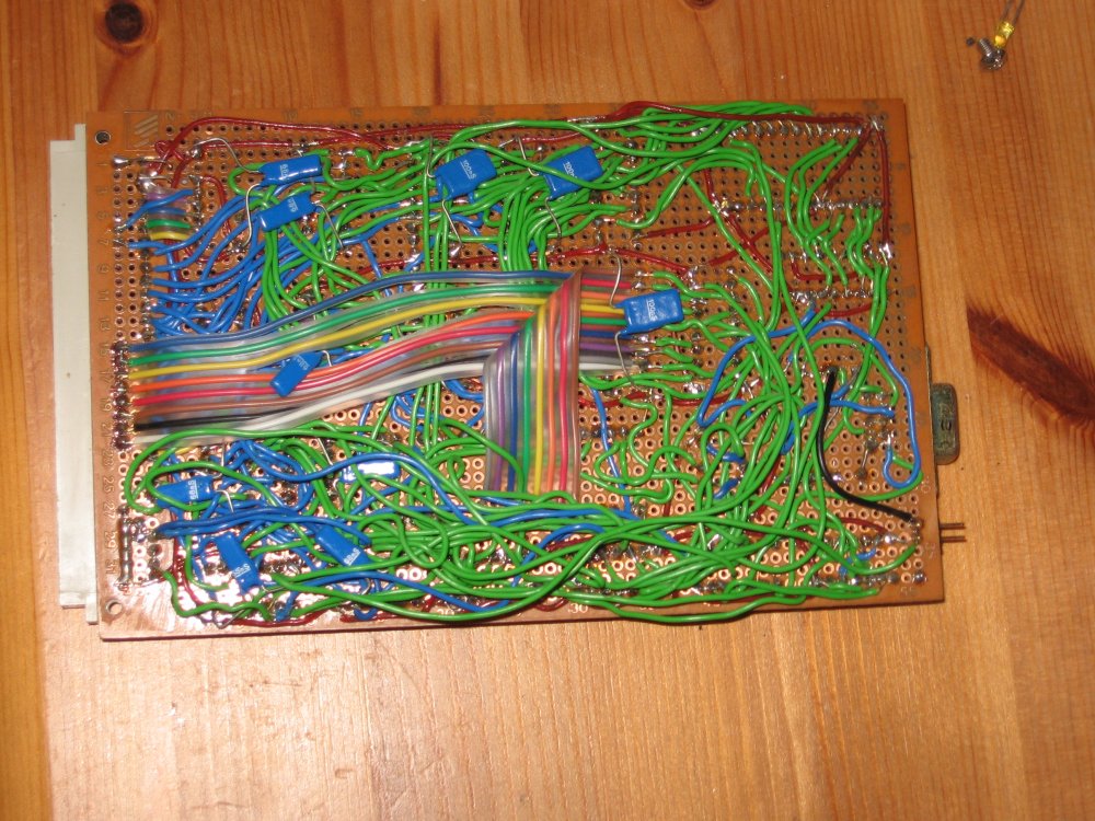
I initially built all the boards using perfboard, meticulously soldering wire by wire.
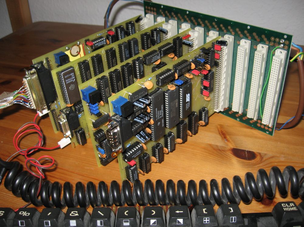
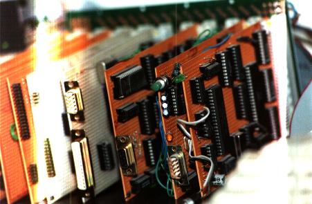
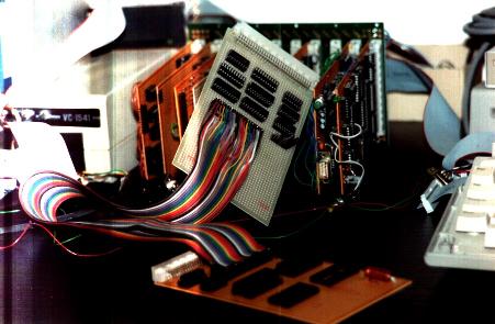
These pictures must have been taken between around 1990 and 1992 where I lived in that student room where they have been taken. It shows an edge of the Atari ST I was using as mass storage device (using an IEEE488 interface I built and that I connected to the Atari's ROM port) and development platform. On this Atari I first wrote the xa65 cross-assembler for my work on GeckOS.
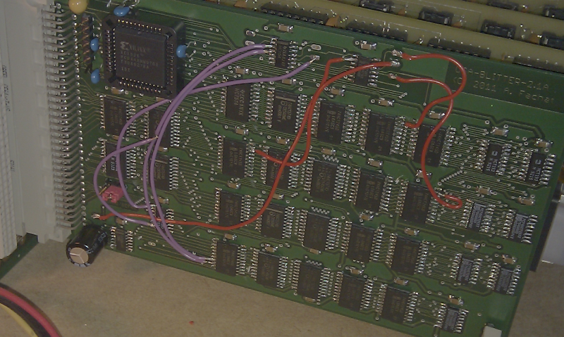
Another picture shows the Emulator board (the grey one in the back) that emulates the 6502 CPU of another computer (a CS/A65 CPU board without MMU, in the front - this very board later became the Gecko prototype board, see also below). The long cable is plugged into the socket where the CPU resides usually on the CPU board and on the special socket on the emulator board. Because the CS/A65 computer with MMU can handle 1 MByte of RAM, the 64 kByte of the emulated CPU are mapped into the memory of the CS/A65 system.
I have been able to test new ROMs for the VC1541 in RAM before burning them into EPROMs. I just replaced the old ROMs on the board with some RAM area from the CS/A computer with the MMU, loaded the new ROM into this RAM (from the CS/A computer) and started the VC1541 DOS.
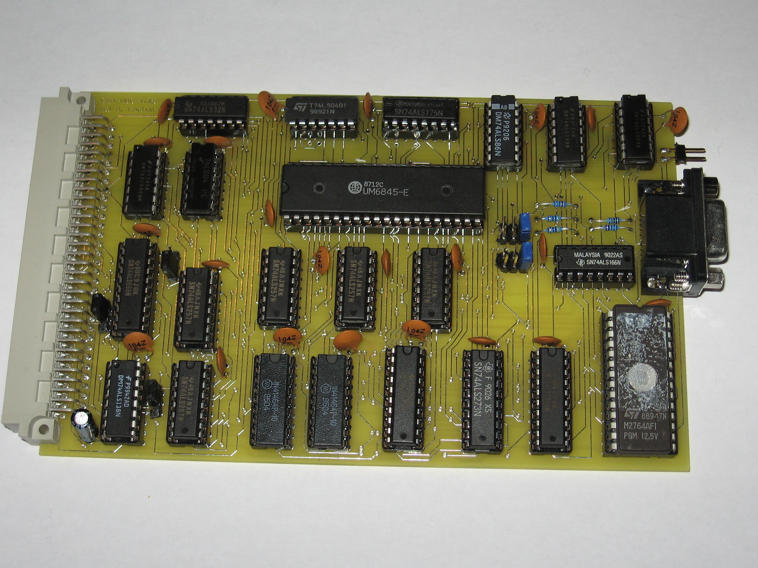
After so many people asked me to give some hardware diagrams to the public, I decided to design and build a simple non-MMU system especially for Web-publishing. So here are the photos of this one, that is now called Gecko:
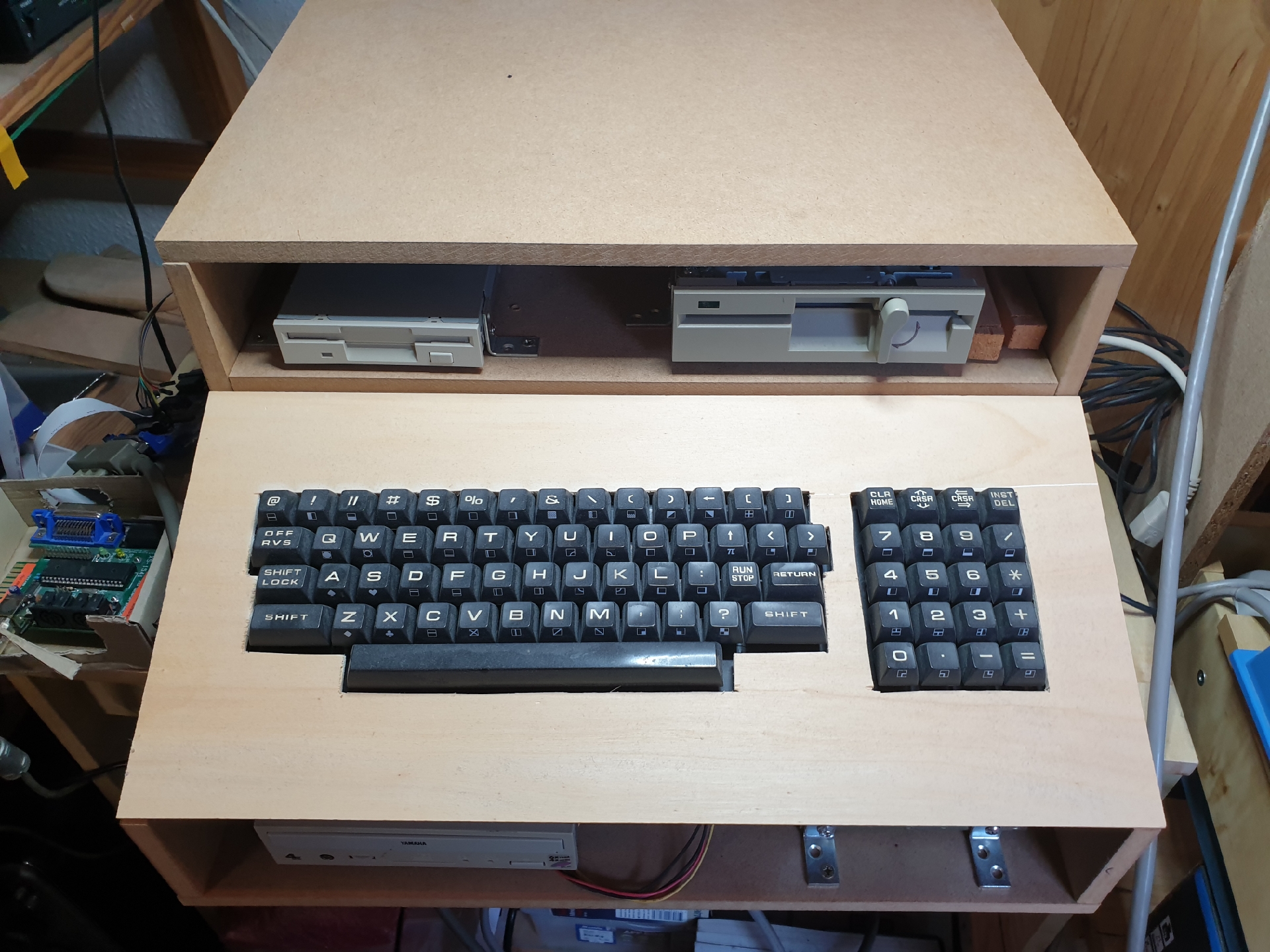
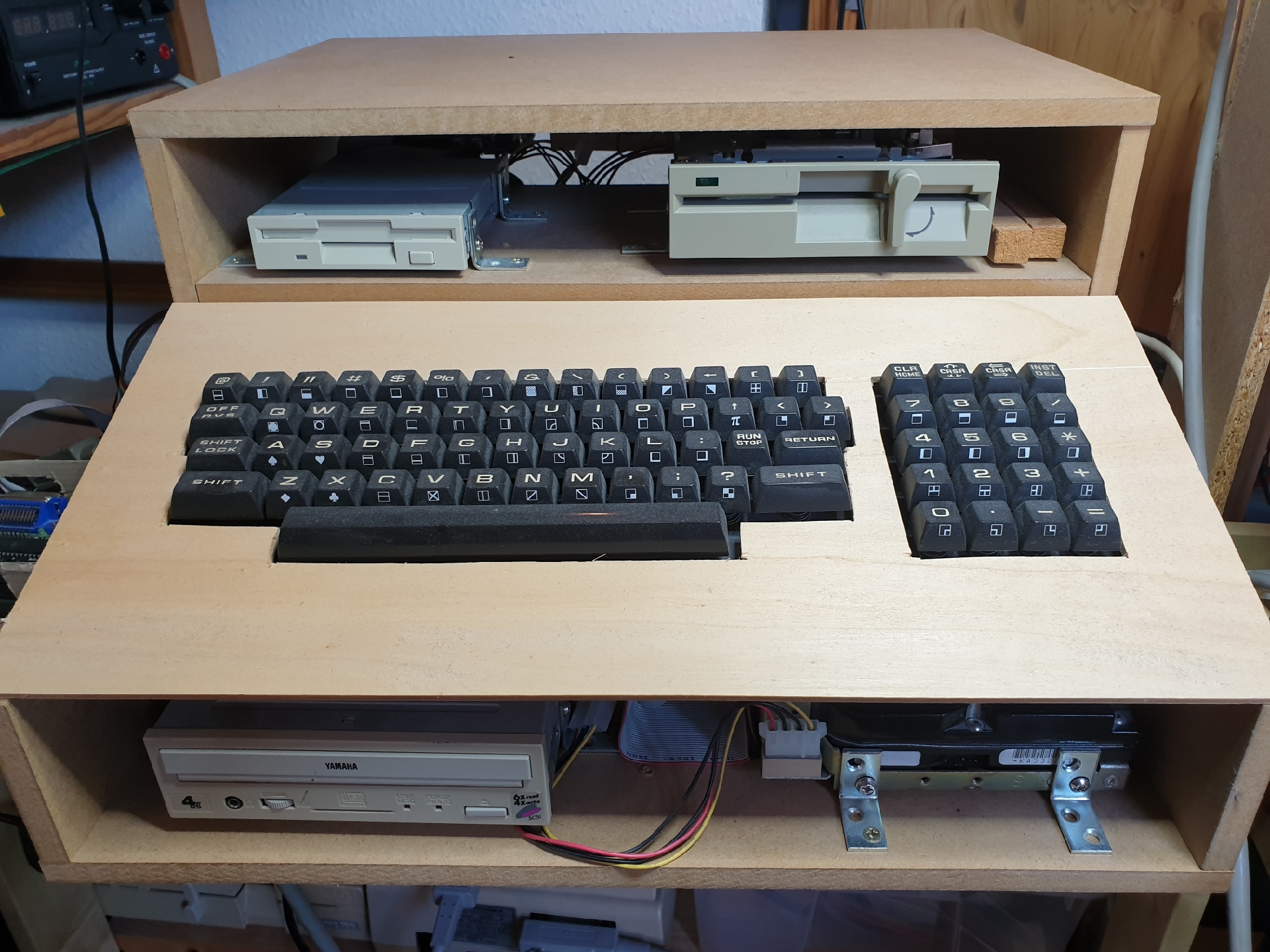
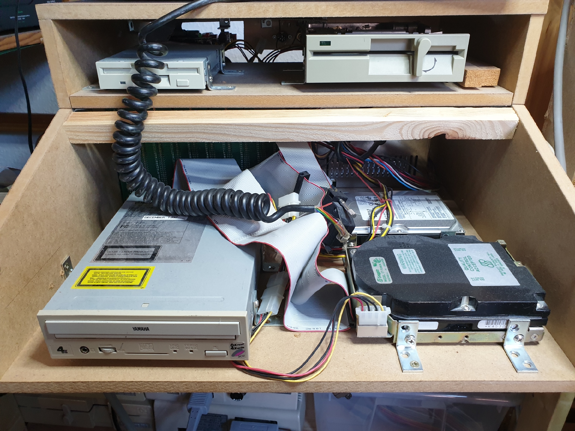
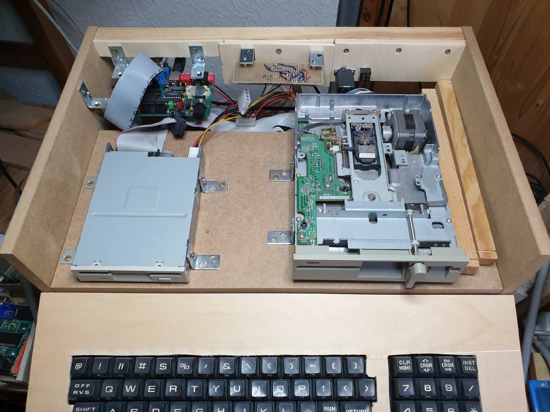
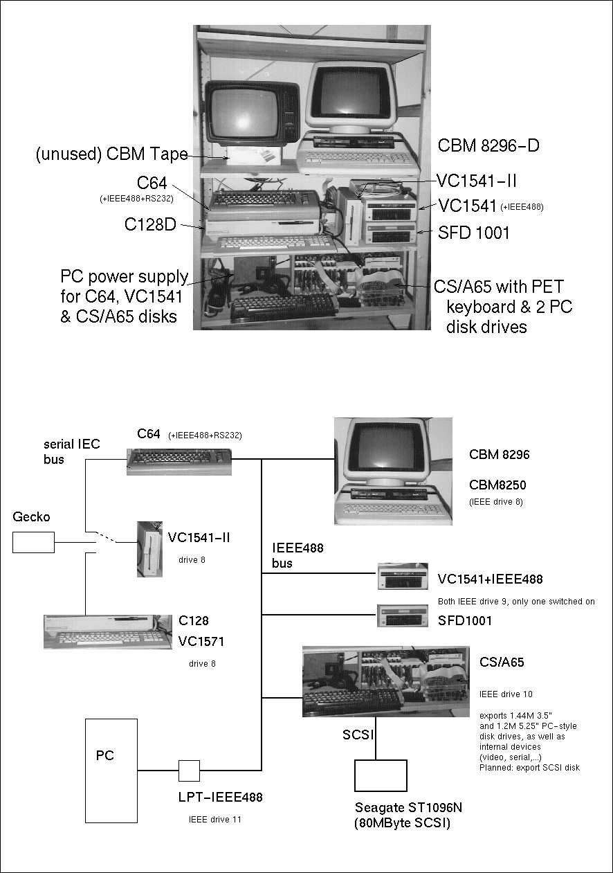
Between 1996 and 1999 I had a very special "tower" configuration of all my 8bit stuff. Everything was connected, and I used the PC as mass storage device and programming platform.
Return to Homepage
Last modified: 2019-09-01