Gecko 2.x
(C) 1997-2010 André Fachat
In 1989, after my first semester at university, I made the first line on the schematics for a small self-designed and self-built computer. This computer, based on the 6502 CPU, has until 1992 become a small computer system
Table of content
The new Gecko system is conformant to this system and has some quite nice features:
- A fast serial RS232 interface, using the 16550 UART with FIFO, known from the PC world.
- A serial IEC bus interface to the Commodore C64 and VC1541
- An interface to infrared LEDs to remote control devices like CD player or TV sets
- A small keyboard interface
- Up to 30 kByte ROM and 32 kByte RAM, with up to 2 kByte fully decoded I/O space
- Bus interface to standard CS/A peripheral interface cards
Software that is completed is:
- GeckOS/A65 Multitasking OS
- Filesystem for the Commodore VC1541 disk drive (in GeckOS/A65)
- Multitasking shell with I/O redirection, including a machine language monitor (running over the serial line
- Device for infrared control
- A TCP/SLIP implementation to mount files from the PC via serial line and SLIP protocol
Later there will be:
- Let the filesystem allow accesses from the serial IEC bus - to access files on the PC from the C64 for example.
You can have a look at the real hardware of my prototype board at my Gallery.
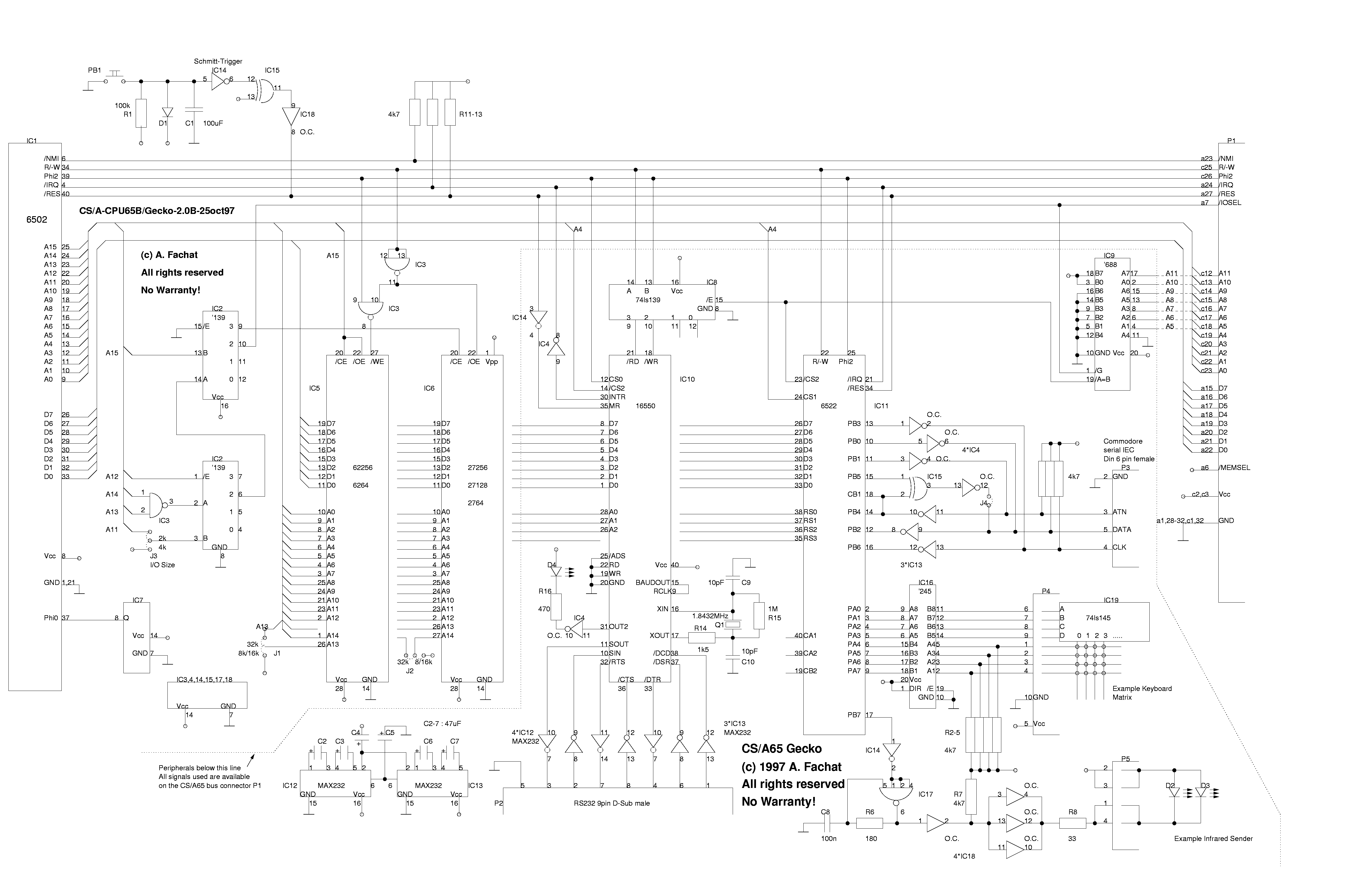
In gecko.ps.gz or gecko.png is a drawn xfig schematics, (in gnuzip'd postscript format or PNG) of the main board that has all the above listed interfaces.
On the left side is the 6502, the CPU. To the right follows an address decoder, that produces the following memory map (which is the standard map for CS/A computers, except for the I/O contents):
$0000 - $7FFF    RAM
$8000 - $E7FF    ROM
$E800 - $EFFF    I/O:
                $EC00-$EC0F     16550A UART
                $EC10-$EC1F     6522 VIA
$F000 - $FFFF    ROM
Further follows the RAM (either 8 or 32 kByte) and the ROM (8, 16 or 32 kByte). The next large chip is the 16550 UART serial interface. The 6522 is a standard chip of the 65xx family and has the rest of the interfaces. On the right side is the CS/A bus connector. The part below the dashed line actually is a simple I/O card, integrated on the CPU card. All signals that cross the dashed line are available on the bus connector, so that you have a simple example of how to implement your own I/O cards (There is an exception - the CPU part and the I/O part share IC14, IC15 and IC18, but that's just for convenience. They are used for the RESET logic. You have to take a Schmitt-Trigger there, and an open collector output. I usually use a 74LS14 with a following 74LS06). Here is the parts list.
One thing is that the 1.8432 MHz crystal Q1, together with R14, R15, C9, and C10 should be replaced with an oscillator like IC7. The oscillator output should be connected to XIN, while XOUT should be not connected.
I used to just connect the crystal to XIN and XOUT, but that doesn't work with all types of crystal - it doesn't start oscillating... It's probably only R15 missing then.
The UART not only has the RS232 interface, but I also use the OUT2 line to drive the system LED: the LED blinks if autodetection tests fail when booting, for example.
The VIA port A is used for a simple keyboard interface. Four lines are driven for output, while four lines can be read. These eight lines are buffered and there is a 10 pin conector with these lines and a 5 Volt power supply. I normally give the 4 output pins to an external BCD-to-decimal decoder with Open collector outputs (74LS145). The up to 10 outputs are then given to a 10x4 keyboard matrix. The 4 output lines are then read from the keyboard. This gives up to 40 keys. When using a 4-to-16 decoder, you can have up to 64 keys.
The VIA PB7 output pin is used to drive the infrared circuitry. If it is high (or set to input) then the circuit is inactive. Otherwise a 40 kHz signal is produced with the help of R6 and C8. This signal is then driven to the infrared LED.
The rest of port B is used for a Commdore compatible serial IEC interface. This interface can be used as floppy or as a master (computer) on the bus. As long if you don't have the software to run it as floppy, disable the ATNA output by opening jumper J4. The ATNA circuitry immediately pulls DATA low if the ATN line goes active and the computer hasn't yet recognized that. But the bus master (sending the ATN) is therefore notified that a device is on the bus.
The software available already is the Operating system GeckOS/A65, together with the shell for this system, and a serial IEC filesystem. Also a small example for a infrared control is also implemented.
If you get the OS/A65 operating system, and have my cross-assembler XA, you have to go to the main directory of the OS/A65 distribution tree and do a "make gecko.rom". This produces the "gecko.rom" file, i.e. a 32 kByte ROM image (with additional CBM two byte load address at the beginning!) This ROM image must be burned into a 32kByte EPROM and put into the Gecko computer.
When the system comes up and detects an error, the LED is giving a blink code. The code can be seen from the definitions in the OS/A file oa1str.def:
/*        Hardware-Errors          */

#define   HE_ZP     <-1         /* Zeropage RAM defective */
#define   HE_RAM    <-2         /* not enough RAM (may be defective) */
#define   HE_IMEM   <-3         /* memory handler init failed */
#define   HE_IDEV   <-4         /* device handler init failed */
#define   HE_ISTR   <-5         /* stream handler init failed */
#define   HE_IENV   <-6         /* environment handler init failed */
#define   HE_ROM    <-7         /* not enough Streams/Envs to handle all
                                   ROM autostart requests */
#define   HE_DEV    <-8         /* error registering ROM device */
#define   HE_TASK   <-9         /* no more active task! */
If the LED blinks 7 times, then it's HE_ROM for example.
After coming up, you have to connect a 9600 baud, 8N1 serial line terminal (or PC with terminal program) to the RS232 interface. You get the prompt of the running shell. In drive A: you have all the registered devices, drive B: shows the ROM contents. Devices are a small key devices, that handles the keyboard interface. If opened for reading, it sends the keycode (0-63) of a pressed key. The null device is a neverfilling trashcan. The spooler device can serialize file transfers. Drive C: is the serial IEC bus drive 8, accessed as a VC1541.
As a program you have irtx on drive B:. It shows a small menu to select a universum TV set, a Sony CD player or a Sony receiver (master). It can then send infrared signals to (my) audio equipment :-)
As the Gecko has no MMU, all programs share the same memory. The following memory locations are used:
Zeropage:
2-14            kernal zeropage
14-32           reserved
32-87           programs

Memory:
$100-$200       Stack
$200-$300       PCBUF (interprocess communications buffer)
$300-$800       kernel buffers, tables etc
$800-$1000      used program space (fsiec buffers, ...)
So in an 8 kByte system, you still have 4 kByte for your purposes. It is recommended to start zeropage use at 128.
There are no changes to the OS/A65 kernel for the Gecko computer. Though, because there is only one 6522, and no special IRQ timer, the following must be considered:
- The kernel needs an interrupt source to be able to preemptively schedule processes. The keydev device uses the VIA timer2 to periodically generate these interrupts. The device itself clears the interrupt again, the kernel never touches the VIA.
- Both, the fsiec filesystem for the serial IEC bus and the irtx program need a timer, and only the VIA timer 1 is left. So they both have to compete for this timer by getting semaphore SEM_T1, which is an alias to SEM_SERIEC. This is a system semaphore to handle concurring requests for system hardware.
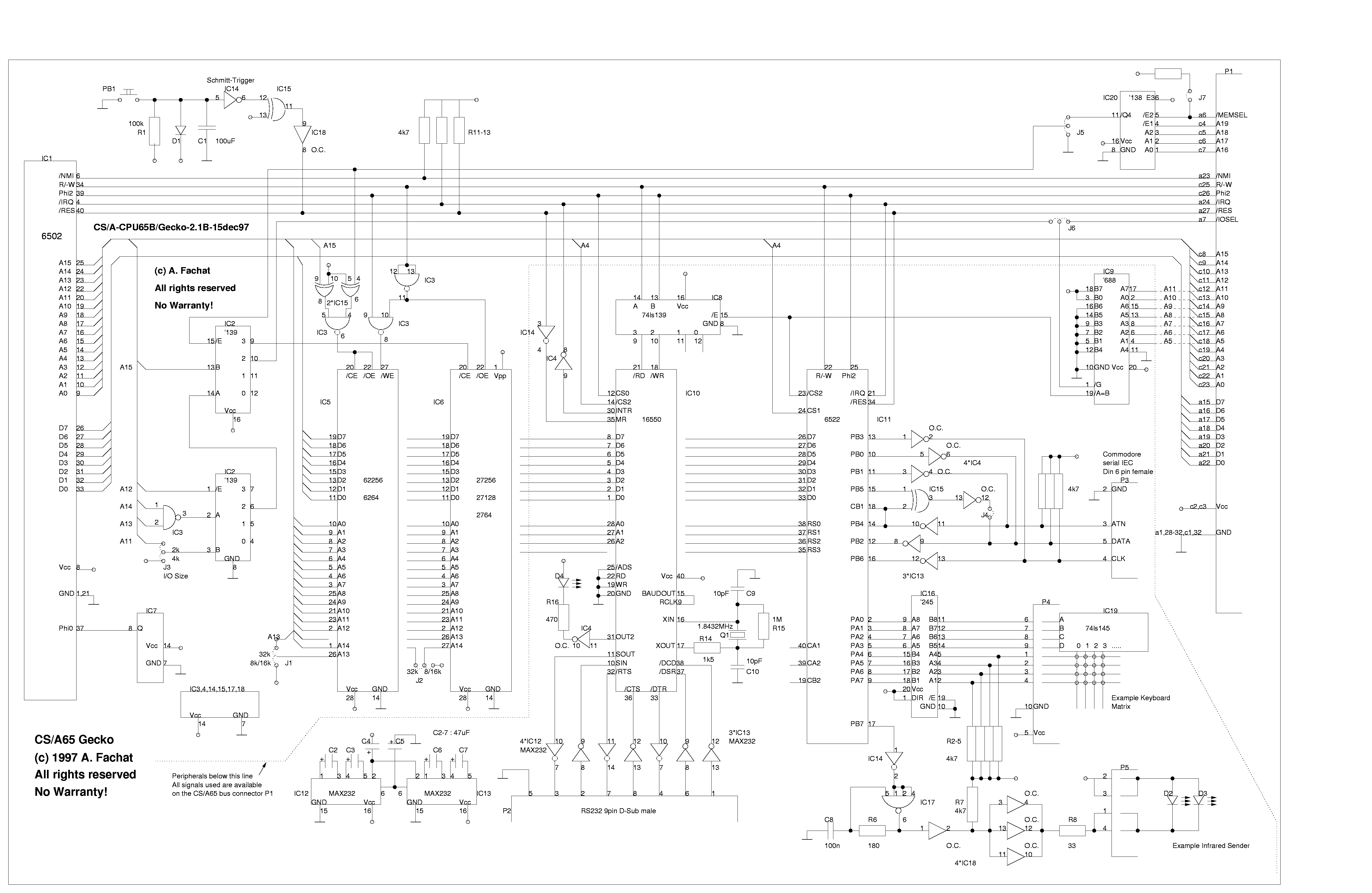
Ok, after toying around with that thing I was wondering if I could use the memory and the I/O in a standard CS/A65 board. I came up with a simple solution with only some jumpers to switch in addition to removing the local CPU. So this board can be tested in a standard CS/A65 system.
The schematics are in gecko2.ps.gz or gecko2.png, and the new parts list is in geckoparts.txt. The description is in geckodesc.txt.
Return to Homepage
Last modified: 2010-06-01